R&S
®
ZVA / R&S
®
ZVB / R&S
®
ZVT Programming Examples
Basic Tasks
Operating Manual 1145.1084.12 – 30 1093
Important remote control features for this program example
The following command sequence illustrates the structure of the remote commands discussed in section
Basic Remote Control Concepts. In particular it shows that:
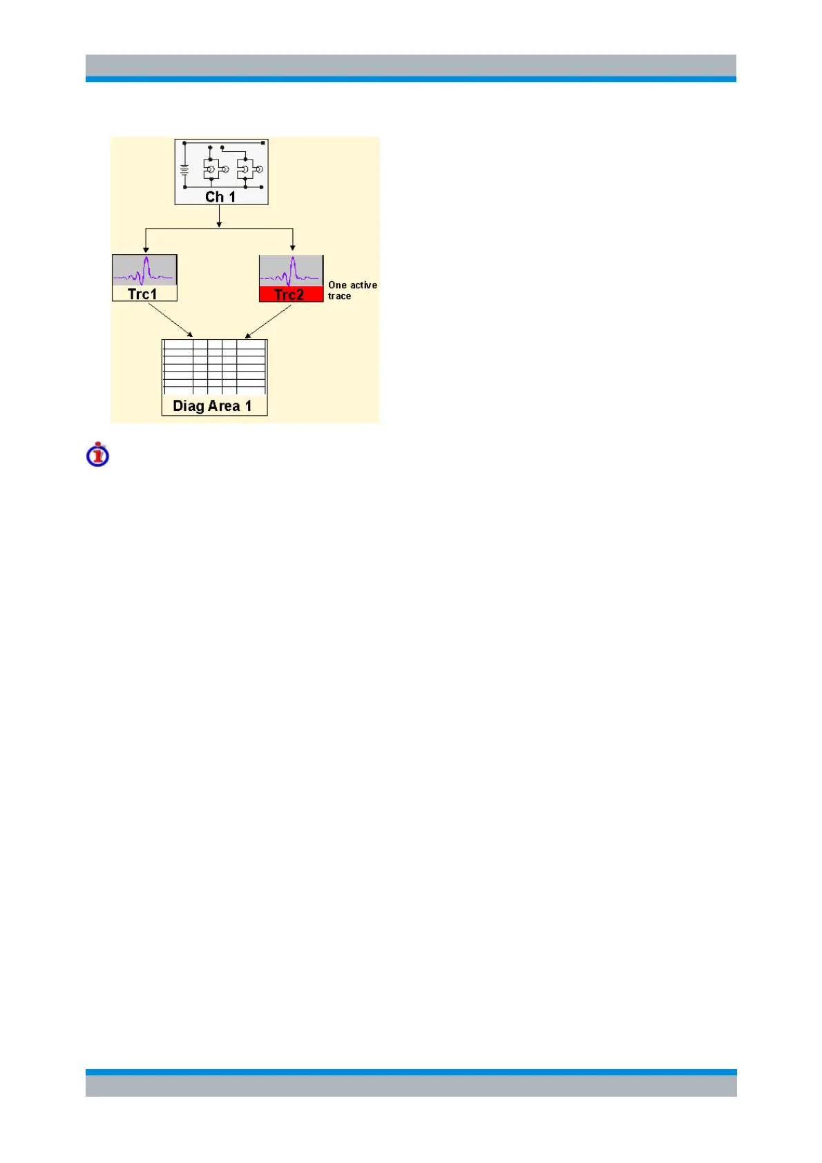
Traces are referenced by trace names. The active trace of a channel is often referenced by the
channel suffix. This simplifies the program syntax, e.g. in the commands for marker settings and
for the limit check.
Diagram areas are referenced by a window suffix <Wnd>. An additional suffix <WndTr> in the
DISPlay:WINDow<Wnd>:TRACe<WndTr>... commands numbers the different traces in a
diagram area.
The analyzer provides several commands allowing a smooth transition between remote and
manual control.
//
//
// 1. Create one channel, two traces, one diagram area
// Reset the instrument, creating the default trace Trc1 in channel 1.
// The default measured quantity is the forward transmission S-parameter S21.
// The default format is dB Mag.
*RST
//
// Create a second trace in channel 1, assign the format Phase,
// and display the new trace in the same diagram area.
CALCulate1:PARameter:SDEFine 'Trc2', 'S21' // the trace becomes the active trace but is not displayed
CALCulate1:FORMat PHASe // the trace is referenced by the channel suffix 1
DISPlay:WINDow1:TRACe2:FEED 'Trc2' // display the second trace, numbering it the second trace in
diagram area no. 1
//