R&S
®
ZVA / R&S
®
ZVB / R&S
®
ZVT GUI Reference
Channel Menu
Operating Manual 1145.1084.12 – 30 245
The port-specific generator step attenuator setting a
step
.
If everything is expressed in dB units, the output power p
el
at each port must be equal to the sum of the
channel power and all port and stimulus-dependent correction factors:
p
el
= p
ch
+ p
b
+ p
Slope
+ p
corr
+ a
step
The automatic attenuator setting algorithm selects a
step
such that the variation range for p
el
is sufficient to
account for the stimulus-dependent variations of p
b
and p
Slope
, and p
corr
. If this is not possible in a particular
subrange of the sweep (e.g. because the sweep settings are such that an excess variation range for p
el
or
a negative attenuation factor a
step
would be required) then the analyzer generates an error message.
"Low Noise" generator attenuation mode
In "Low Noise" mode, the automatic attenuator setting algorithm is modified in order to minimize the
broadband noise in the generator signal. The modification can narrow the dynamic range that the
generator covers without switching the attenuator. Use this mode if the following criteria apply:
Your test setup contains a broadband power meter (that you use e.g. for a power calibration).
Your generator levels are not significantly above the broadband noise level; see table below.
Your analyzer supports a large frequency range (this applies to the high-frequency models, see
table below).
The amount of broadband noise in the generator signal increases with the total bandwidth of the network
analyzer. The following table gives an overview for the different R&S ZVA analyzer models.
–21 dBm (< 24 GHz) and –25 dBm (> 24 GHz)
–20 dBm (< 24 GHz) and –13 dBm (> 24 GHz)
The value selected by the automatic attenuator setting algorithm (in "Auto" or "Low Noise" mode) can
be readout via the remote command SOURce<Ch>:POWer<Pt>:ATTenuation:AUTO:VALue?
A new system error correction is recommended whenever the step attenuator settings are changed. A
change of the generator step attenuator settings may also occur in Auto mode; see above.
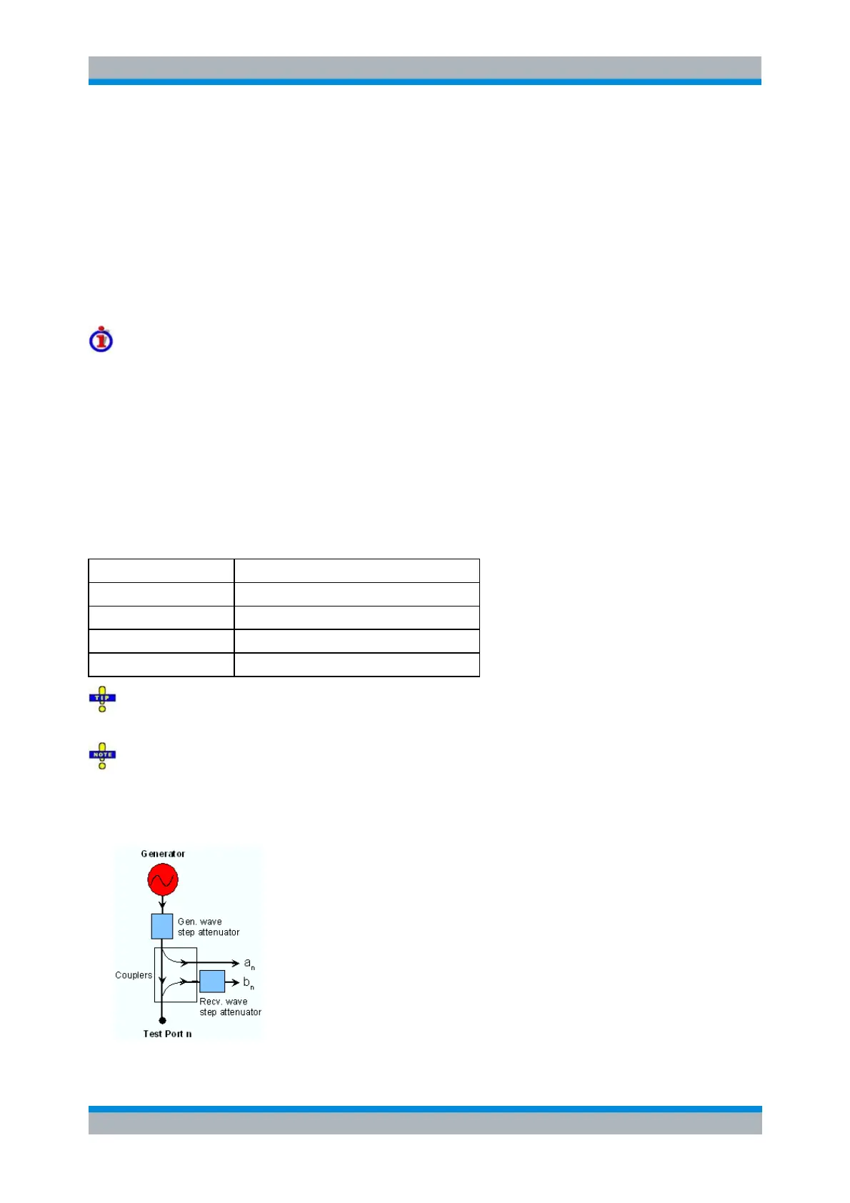
The position and function of the step attenuators is illustrated in the following figure. The analyzer
measures both the attenuated generated waves and the attenuated waves received from the DUT.