R&S
®
ZVA / R&S
®
ZVB / R&S
®
ZVT GUI Reference
Channel Menu
Operating Manual 1145.1084.12 – 30 349
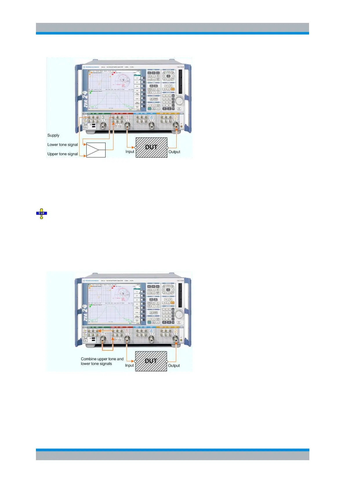
The lower tone signal is generated at port 1, the upper tone is provided by a second source (port 3). Both
signals are combined externally and fed to the SOURCE IN connector at port 1. Thus the superimposed
signals are available at test port 1 and can be fed to the DUT input. The intermodulation quantities can be
measured at the DUT input (wave a
1
) or at the DUT output (wave b
2
).
You can use different ports, however, the generators of the source ports must not be coupled. You may
also use an external generator for the upper tone signal.
On R&S ZVA67 and on R&S ZVA24/40 network analyzers with four ports and four generators (order
nos. 1145.1110.28/48), all ports have independent internal sources. You can perform intermodulation
measurements with an arbitrary combination of two source ports.
Alternative test setup
The following test setup does not require an external coupler but provides a reduced dynamic range.
The lower tone from port 1 and the upper tone from port 3 are combined using the directional coupler of
port 3. Ports 1 and 3 are connected as follows: SOURCE OUT (1) to MEAS OUT (3) and Port 3 to
SOURCE IN (1). The superimposed signals are available at test port 1 and can be fed to the DUT input.
The intermodulation quantities can be measured at the DUT input (wave a
1
) or at the DUT output (wave
b
2
).
You can use different ports, however, the generators of the source ports must not be coupled. You may
also use an external generator for the upper tone signal.