R&S
®
ZVA / R&S
®
ZVB / R&S
®
ZVT GUI Reference
Channel Menu
Operating Manual 1145.1084.12 – 30 358
via Prepare Measurement of IM Order in the Define Intermod Dist Meas dialog. These power
calibrations are required for the receiver calibration in step 3 (unless Prepare Enhanced Wave
Corr was selected in the Define Intermod Dist Meas dialog) and for the measurement of
intermodulation products at the DUT input.
c. If in addition to the intermodulation measurement a mixer measurement is set up as well, all
frequency ranges mentioned under a. and b. plus the upper tone range will be calibrated in the IF
range as well unless Prepare Enhanced Wave Corr is selected in the Define Intermod Dist Meas
dialog. In this case the IF frequency ranges are neither needed for intermodulation products at the
DUT input (as those are measured in the RF range) nor for the receiver calibration (as a source
power calibration will be performed at the receiving port).
d. If in a non mixer measurement the upper tone is driven by an external generator and in the Define
Intermod Dist Meas dialog Ext. Dev. is chosen as Two Tone Output and Prepare Enhanced Wave
Corr is not selected, the upper tone frequency range is calibrated both at the lower tone and the
upper tone port. At the upper tone port a flatness calibration is required as that port will be driving
this frequency during actual measurements. At the lower tone port a reference receiver calibration
is performed which is required for the receiver power calibration in step 3 and which cannot be
performed at the external generator.
During these calibrations the upper tone port is switched off.
Power considerations
The directional coupler introduces a coupling loss of approx. 10 dB. Adjust the port power settings to
account for this attenuation and possible additional effects; see Level Handling during Power Calibration.
2. Source power calibration for the upper tone port. The test setup from step 1 is maintained. In this step
the upper tone range will be calibrated with port 3 driving. The lower tone port is switched off during this
calibration. For a mixer measurement only the RF range of the upper tone will be calibrated in this step.
3. Power calibration for the receiving port. If Prepare Enhanced Wave Corr is selected in the Define
Intermod Dist Meas dialog, a source power calibration will be performed at the receiving port, otherwise a
receiver power calibration will be performed.
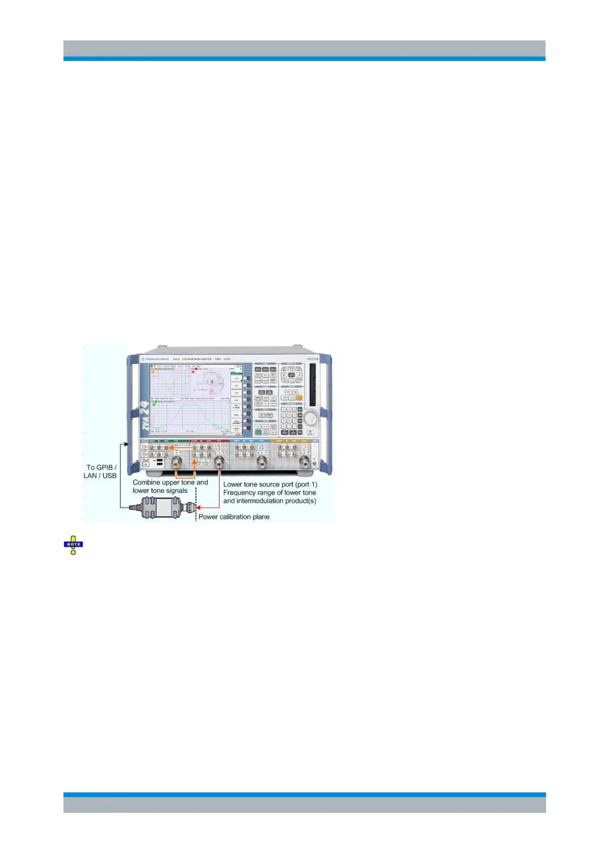
For a receiver power calibration no external device is needed. The receiver (port 2) is calibrated using the
source signal from port 1 (lower tone signal, red) calibrated in the first step.
For a source power calibration a power meter has to be connected to port 2 (not shown in the picture
below). Both for a receiver power calibration and a source power calibration the calibration encompasses
the lower and upper tone frequency range as well as the frequency range for all lower and upper
intermodulation products which have been selected via Prepare Measurement of IM Order in the Define
Intermod Dist Meas dialog. If in addition to the intermodulation measurement a mixer measurement is set
up as well, only the IF frequency ranges will be measured.