R&S
®
ZVA / R&S
®
ZVB / R&S
®
ZVT GUI Reference
Channel Menu
Operating Manual 1145.1084.12 – 30 392
reference Z
0
are divided by two (see table below).
Switching between the two stimulus power modes changes the single ended power levels by 3 dB. The
channel power setting P
ch
(Channel – Stimulus – Power) remains unchanged.
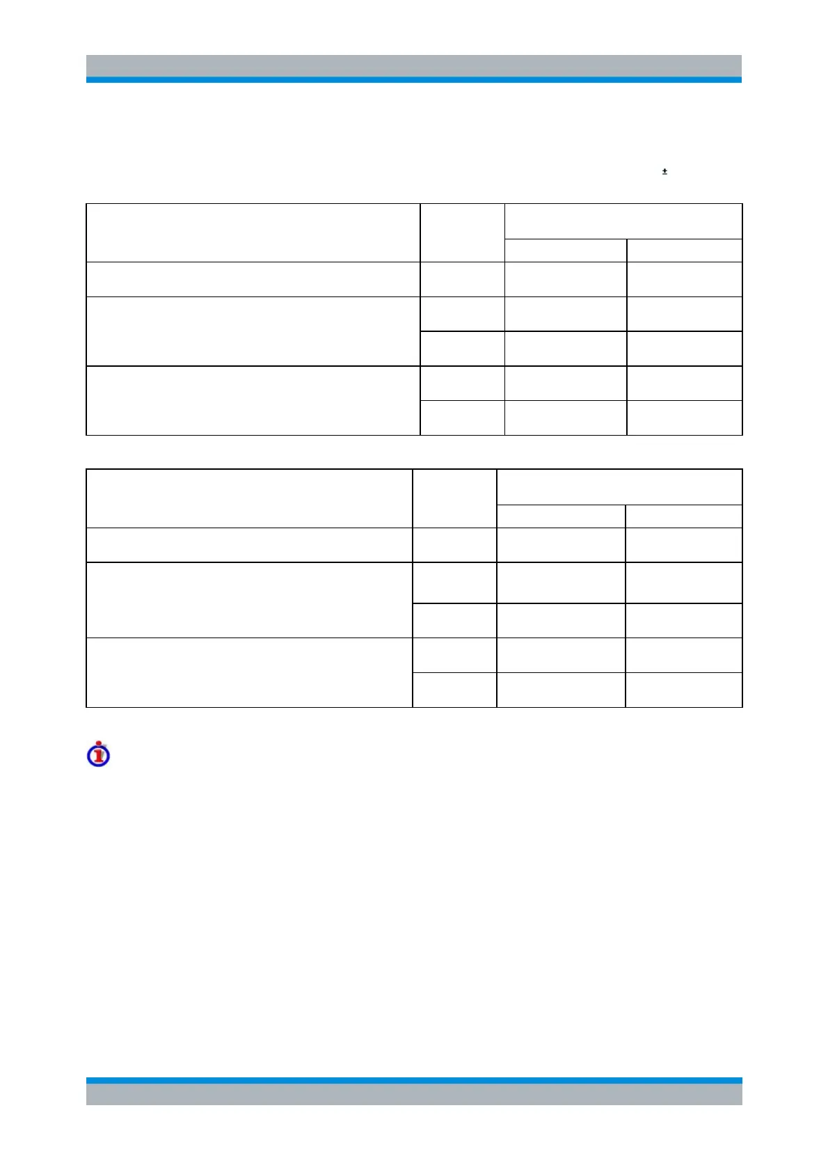
Nodal generator power levels and voltages
at physical ports
Virtual differential mode
P
ch
( = U
d
2
/ Z
0
)
U
d
/2 + U
c
(= U
d
)
*)
True differential mode, "Same Differential and Common Mode
Voltages as in Single-Ended Mode"
True differential mode, "Apply to Differential (Z
d
= 2Z
0
) and
Common Mode (Z
c
= Z
0
/2) Waves"
*) This entails the condition U
d
= 2 * U
c
Modal generator power levels and voltages
at balanced port
Virtual differential mode
True differential mode, "Same Differential and Common Mode
Voltages as in Single-Ended Mode"
True differential mode, "Apply to Differential (Z
d
= 2Z
0
) and
Common Mode (Z
c
= Z
0
/2) Waves"
Avoiding possible problems at very large or very low source power levels
1st scenario: Large source power levels
The maximum output power is not always exactly the same for different physical test ports. The deviations
are generally small (< 1 dB).
If the network analyzer in true differential mode is operated in the vicinity of the maximum channel power
(> +5 dBm), a message "Port<n> power unleveled" may indicate that one of two combined physical ports
cannot provide the required source power. The measurement is not aborted, however, the analyzer is no
longer capable of providing accurate balanced waves.
If you operate the analyzer close to its maximum power, first check the reference channels (a-waves) and
ensure a 1 dB reserve over the entire sweep range.
2nd scenario: Small source power levels
To generate equal source power levels, the signal-to-noise ratio at each port must be sufficiently high. At