R&S
®
ZVA / R&S
®
ZVB / R&S
®
ZVT GUI Reference
Channel Menu
Operating Manual 1145.1084.12 – 30 393
very low levels (<–30 dBm) and large IF bandwidths, a message "Port<n> power unleveled" may indicate
that the signal-to-noise ratio at one of the ports is too low. Again, the measurement is not aborted,
however, the analyzer is no longer capable of providing accurate balanced waves.
If you operate the analyzer at very low output power settings, reduce the IF bandwidth to 1 kHz or below.
The source power mode is a global setting. It is defined in the Power tab of the System Configuration
dialog.
SOURce<Ch>:TDIF:WAVes SENDed | DCMode
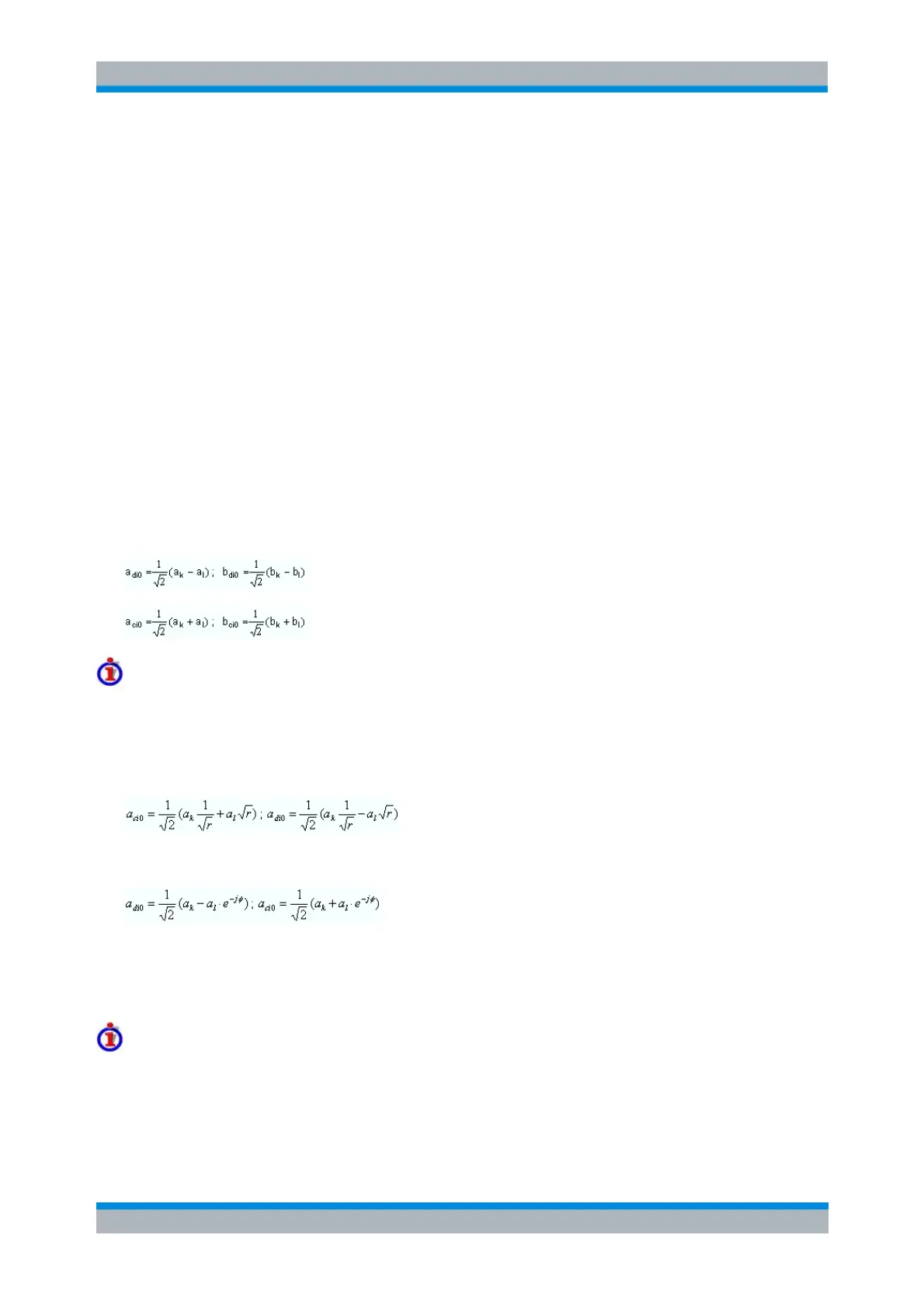
Wave Quantities and Ratios in True Differential Mode
In true differential mode, the analyzer can determine the balanced wave quantities and ratios for all
balanced ports. The balanced quantities appear in the More Wave Quantities or More Ratios dialog as
soon as the true differential mode is active.
Assume that a balanced port numbered i comprises the two physical ports k and l. To obtain the balanced
wave quantities for port i, the analyzer measures the unbalanced wave quantities at ports k and l. The
differential mode waves a
di0
and b
di0
and the common mode waves a
ci0
and b
ci0
can be calculated from the
unbalanced waves using the following equations:
Possible modification for amplitude and phase imbalance sweep
In an amplitude imbalance or phase imbalance sweep, it is possible to compensate the a waves for the
known phase imbalance φ and the amplitude imbalance r = | a
k
/ a
l
|. This modifies the formulas for the
balanced wave quantities as shown below.
For an amplitude imbalance sweep with known imbalance r:
For a phase imbalance sweep with known imbalance φ:
The amplitude and phase imbalances are known quantities (sweep parameters). The unbalanced waves
a
k
and a
l
are measured in the reference channels. With ideal unbalanced waves and no additional
disturbing effects, the compensated balanced stimulating a-waves remain constant over the entire sweep
range.
Renormalization of port impedances
In the default scenario where the reference impedances for the differential and common mode are equal
to Z
d
= 2 Z
0
and Z
c
= 1/2 Z
0
, the waves a
di0
, b
di0
, a
ci0
and b
ci0
correspond to the true balanced waves at port
i. With arbitrary reference impedances for the balanced waves, an additional renormalization step is
necessary: