R&S
®
ZVA / R&S
®
ZVB / R&S
®
ZVT GUI Reference
Trace Menu
Operating Manual 1145.1084.12 – 30 116
wave is fed to the output port (port 2) of the DUT (reverse measurement).
b1 Src Port 2 is the wave received at test port 1. In a standard S-parameter measurement, this
wave is transmitted at port 2 of the DUT (reverse measurement).
b2 Src Port 2 is the wave received at test port 2. In a standard S-parameter measurement, this
wave is fed to the output port (port 2) of the DUT (reverse measurement).
The analyzer can also measure wave quantities for other source ports; see More Wave Quantities.
CALCulate<Ch>:PARameter:MEASure "<Trace_Name>", "A1" |
Create new trace and select name and measurement parameter:
CALCulate<Ch>:PARameter:SDEFine "<Trace_Name>", "A1" | ...
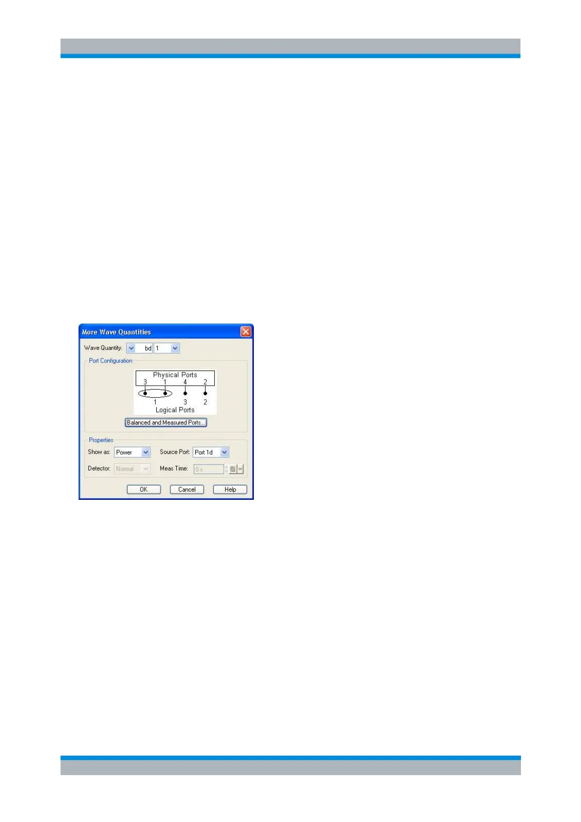
More Wave Quantities
Opens a dialog to define and select arbitrary wave quantities for different detectors and source ports or
higher port numbers. In true differential mode, the dialog also offers balanced wave quantities.
The notation for wave quantities and the functionality of the More Wave Quantities dialog is analogous to
the definition of S-parameters.
Wave Quantity selects the type (left pull-down list) and the port number assignment (right pull-
down list) of the wave quantity. Balanced wave quantities are only available if the True Differential
Mode is active; see background information below. The output (transmit) or input (receive) port
number of the analyzer (corresponding to the input (stimulus) or output (response) port number of
the DUT, respectively) is selected in the right pull-down list. The range of output and input port
numbers depends on the analyzer model.
Show as selects the physical unit of the displayed trace. It is possible to display the measured
Voltage V or convert the wave quantity into an effective power according to P = V
2
/Re(Z
0
). Z
0
denotes the reference impedance of the source port (for wave quantities a
n
) or of the receive port
(for wave quantities b
n
). The reference impedances are defined in the Port Configuration dialog.
This function is also available for memory traces where the remaining control elements of the
dialog are grayed.
Source Port contains all analyzer ports or external generators which can be used as a source for
the stimulus signal. The list contains all analyzer ports Port 1 to Port n. Generators (Gen 1, Gen 2,
...) must be configured explicitly in the System Configuration – External Generators dialog before