R&S
®
ZVA / R&S
®
ZVB / R&S
®
ZVT GUI Reference
Channel Menu
Operating Manual 1145.1084.12 – 30 396
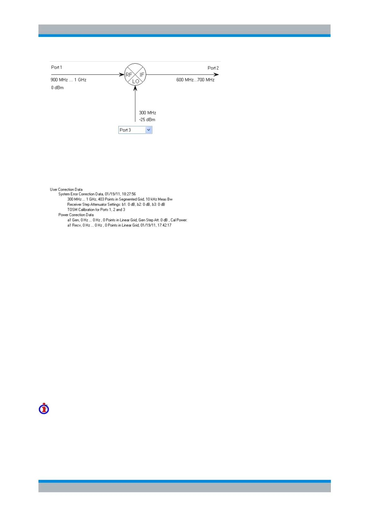
Calibration kits do not contain frequency-converting two-port standards so that any system error correction
is performed at equal source and receiver frequencies. However, if a scalar mixer measurement is active,
the analyzer automatically performs the system error correction in both the RF and the IF frequency
range. The number of points for the calibration sweep is doubled. In the Calibration Manager dialog, the
calibrated frequency range is referred to as a "Segmented Grid".
A subsequent source or receiver power calibration not only calibrates the source power and the receiver
but is also used to adjust the normalization of the system error corrections in both power ranges. For this
reason, the measurement steps must be performed in the following order:
1. Activate the frequency-converting (e.g. scalar mixer) mode.
2. Perform a full n-port calibration for all ports involved.
3. Perform a power calibration (for true differential ports, once per balanced port).
4. Activate true differential mode.
4. Connect the DUT in order to perform measurements.
Amplitude Imbalance Sweep
To ensure proper operation, differential devices need a pure differential stimulus signal. Unequal
attenuation or loss in the conductors of the balanced input or output line leads to a phase or amplitude
imbalance of the stimulus signal. If the device under test is linear, the effects of this imbalance can be
calculated from the mixed-mode S-parameters without performing an additional measurement. For
nonlinear devices, however, the effects may be unpredictable. Therefore, the option True Differential
Mode incorporates the ability to generate differential and common mode signals with a physical amplitude
or phase imbalance. Moreover, the imbalance can be swept over a user-defined range.
Characteristics of the sweep
The amplitude imbalance sweep is performed as follows:
The amplitude imbalance is defined as r dB = 20 log (|a
k
/a
l
|) dB, where a
k
and a
l
are the wave
quantities of the physical ports with the higher and lower port numbers.
The selected amplitude imbalance is applied to both differential and common mode signals. The