R&S
®
ZVA / R&S
®
ZVB / R&S
®
ZVT GUI Reference
Channel Menu
Operating Manual 1145.1084.12 – 30 394
The reference impedances Z
c
and Z
d
can be entered in the Balanced Ports and Port Groups dialog.
CALCulate<Ch>:PARameter:SDEFine 'AS1D2S' |
S-Parameters in True Differential Mode
The mixed-mode S-matrix elements that the analyzer acquires in true differential mode correspond to the
mixed-mode matrix elements obtained in virtual differential mode, however, the analyzer uses true
differential and true common mode stimuli at each balanced port of the DUT.
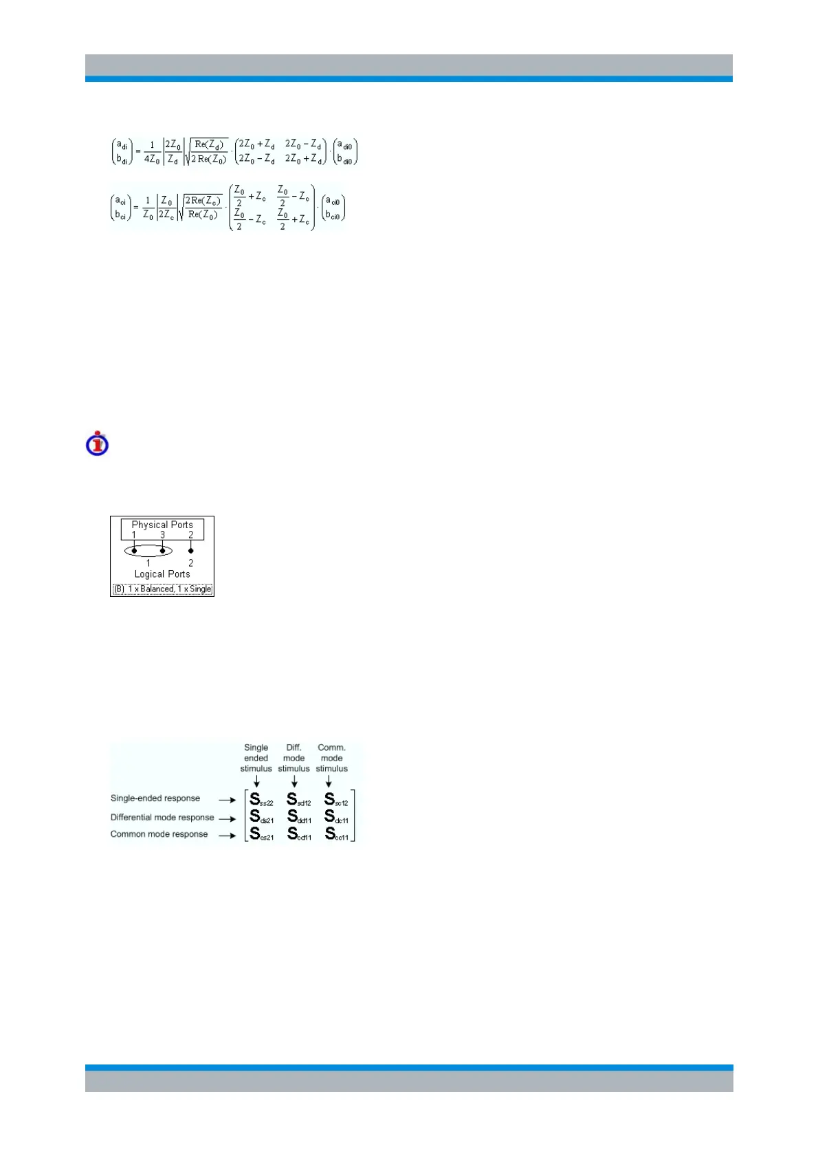
Example: 3x3 mixed-mode S-matrix
Suppose that a three-port analyzer is configured for one balanced and one single-ended port as shown
below:
To obtain the complete mixed-mode S-matrix, the analyzer generates the following stimulus signals:
1. Differential mode signal fed to balanced port no. 1 of the DUT
2. Common mode signal fed to balanced port no. 1 of the DUT
3. Unbalanced signal fed to single-ended port no. 2 of the DUT
The DUT is fully characterized by the following mixed mode matrix:
For linear DUTs, the S-matrices acquired in virtual and in true differential mode are expected to be equal.
The following figure shows a comparison for the transmission coefficient S
sd12
. The red trace was
measured in true differential mode. The blue trace (below, measured in virtual differential mode) is almost
identical over the entire sweep range.