standards. If the calibrated frequency range is small enough, the calibration is valid as soon as the
calibration.
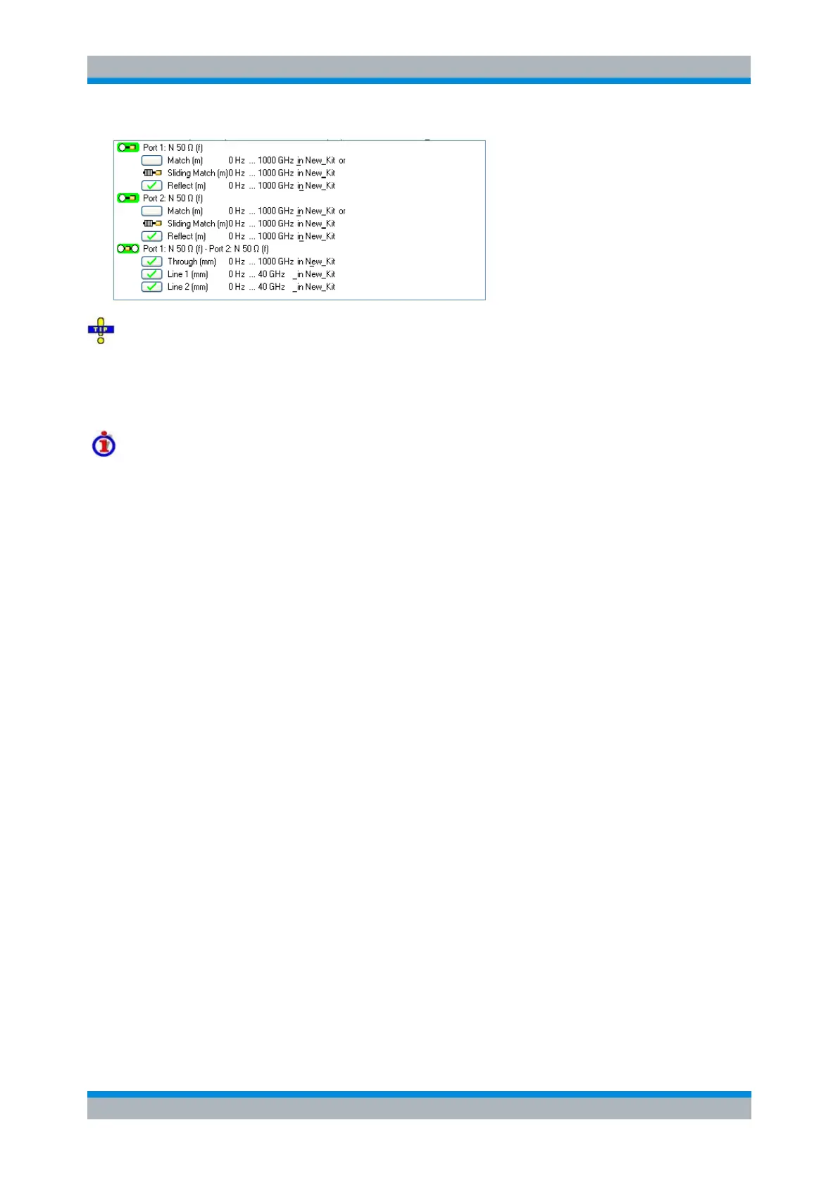
Defining cal kits with several Line standards
Predefined calibration kits usually do not provide several Line standards with different lengths. To
generate a calibration kit appropriate for TRL calibration with two or three Lines, proceed as
described in Creating a user-defined calibration kit. Click Optimize Line Freq Ranges in the View
Calibration Kit dialog to check the transition frequencies between the Lines that the analyzer
calculates according to the rules described above.
Low-frequency extension with TRM
TRL calibration becomes inaccurate if the electrical length difference between Line and Through
standard corresponds to a phase shift below 20°. In practice this means that TRL is only
practicable above a threshold frequency f
TRM
which depends on the delays of the longest Line and
Through standards. The threshold frequency is given by:
f
TRM
= 1/[18*(d
long
– d
Through
)]
where d
long
denotes the delay of the longest of the used Line standards, d
Through
the delay of the
Through. For waveguide standards, a modified formula applies; see Frequency for waveguide
standards. At frequencies below f
TRM
, TRL calibration is automatically replaced by TRM, provided
that the necessary calibration data has been acquired. For a line with l
long
= c
0
*d
long
= 16.666 cm,
the threshold frequency is f
TRM
= 100 MHz.
TRL calibration with low-frequency TRM extension
Accuracy conditions for the Line(s)
The length error of the Line, converted into a transmission phase error, must be below the
minimum difference to the singularity points 0 deg or 180 deg multiplied by two. Suppose that an
approximately known Line standard causes a transmission phase of 30 deg at the start frequency
and of 160 deg at the stop frequency of the sweep. Its length error must cause a phase difference
below (180 deg – 160 deg)*2 = 40 deg.