R&S
®
ZVA / R&S
®
ZVB / R&S
®
ZVT Command Reference
SCPI Command Reference
Operating Manual 1145.1084.12 – 30 631
For n < k the response values of the lower limit line segments no. 2, 4 to 2*n are updated, the
lower limit line segments 2*n+2, 2*n+4,..., 2*k are generated with default stimulus values (see
CALCulate<Chn>:LIMit:CONTrol[:DATA]. In addition, the missing upper limit line segments
2*n+1, 2*n+3,..., 2*k–1 are generated with default stimulus and response values
Channel number used to identify the active trace.
Pair(s) of response values.
Almost no restriction for limit segments; see Rules for Limit Line Definition.
[dB]
–
The response value of a segment that is created implicitly, e.g. an upper limit
line segment, is –20 dB.
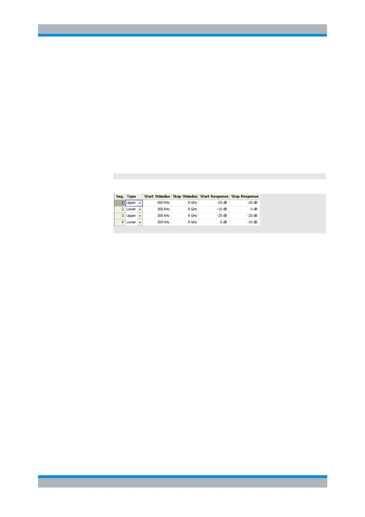
CALC:LIM:LOW -10, 0, 0, -10
Define the following lower and (default) upper limit line segments:
CALC:LIM:DISP ON
Show the limit line segments in the active diagram.
CALCulate<Chn>:LIMit:LOWer:FEED
<stimulus_offset>,<response_offset>[,<trace_name>]
Generates a lower limit line using the stimulus values of a data or memory trace and specified offset
values.
Channel number used to identify the active trace. This trace provides the
stimulus data for the limit line unless another trace <trace_name> is
specified.
Stimulus offset value, used to shift all imported limit line segments in
horizontal direction.
-1000 GHz to +1000 GHz [Hz]
Response offset value, used to shift all imported limit line segments in vertical
direction.
-10
12
dB to +10
12
dB [dB]
Name of the selected trace as used e.g. in
CALCulate<Ch>:PARameter:SDEFine. If no trace name is specified the
analyzer uses the active trace no. <Chn>.
Device-specific, no query.