R&S
®
ZVA / R&S
®
ZVB / R&S
®
ZVT Command Reference
SCPI Command Reference
Operating Manual 1145.1084.12 – 30 639
CALC:LIM:STAT ON; TTL2 ON
Switch the limit check on and activate the TTL out pass 2 signal.
CALCulate<Chn>:LIMit:UPPer[:DATA]
<numeric_value>,<numeric_value>{,<numeric_value>,<numeric_value>}
Defines the response (y-axis) values of the upper limit line and/or creates new limit line segments.
The commands CALCulate<Chn>:LIMit:LOWer[:DATA] and
CALCulate<Chn>:LIMit:UPPer[:DATA] use a fixed numbering scheme for limit line segments: Upper
limit line segments are assigned odd numbers (1, 3, 5,...), lower limit line segments are assigned even
numbers (2, 4, 6,...).
Rules for creating segments
The following rules apply to an active trace with n existing upper and n existing lower limit line segments:
An odd number of values is rejected; an error message –109,"Missing parameter..." is generated.
An even number of 2*k values updates or generates k upper limit line segments.
For n > k the response values of all existing upper limit line segments no. 1, 3, ...,2*k–1 are
updated, the existing upper and lower limit line segments no. 2*k+1, ..., 2*n are deleted. The
existing lower limit line segments no. 2, 4, 2*k are not affected.
For n < k the response values of the upper limit line segments no. 1, 3 to 2*n–1 are updated, the
upper limit line segments 2*n+1, 2*n+3,..., 2*k–1 are generated with default stimulus values (see
CALCulate<Chn>:LIMit:CONTrol[:DATA]. In addition, the missing lower limit line segments
2*n+2, 2*n+4,..., 2*k are generated with default stimulus and response values
Channel number used to identify the active trace.
Pair(s) of response values.
Almost no restriction for limit segments; see Rules for Limit Line Definition.
[dB]
–
The response value of a segment that is created implicitly, e.g. an lower limit
line segment, is –20 dB.
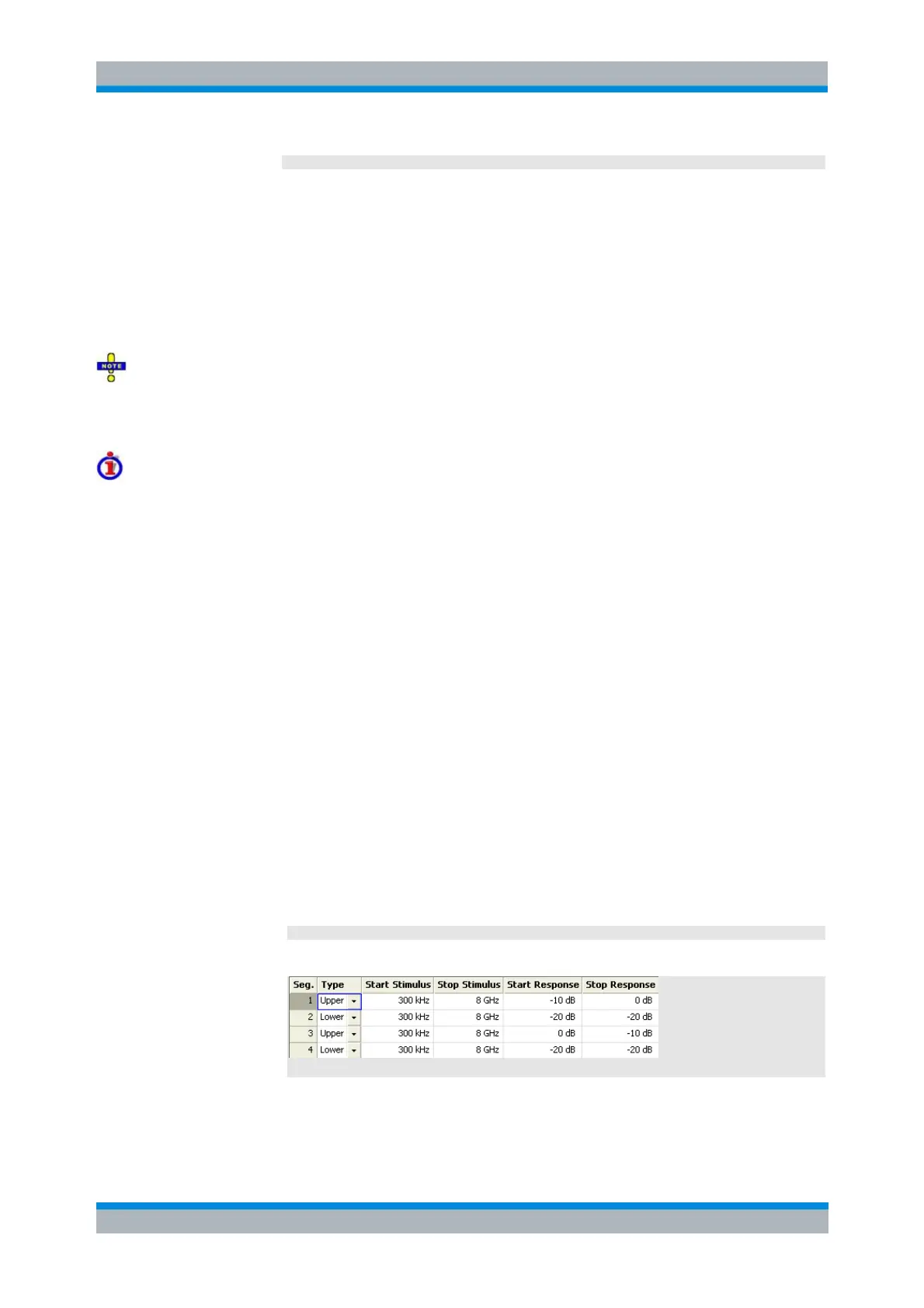
CALC:LIM:UPP -10, 0, 0, -10
Define the following upper and (default) lower limit line segments:
CALC:LIM:DISP ON
Show the limit line segments in the active diagram.