8
8-30
INPUT/OUTPUT PORTS AND PIN FUNCTIONS
32180 Group User’s Manual (Rev.1.0)
OSC-VCC,
VCCE, VDDE
VCC-BUS,
EXCVCC, EXCVDD
MOD0, MOD1
FP
JTDI, JTCK, JTMS
JTDO
RESET#, XIN, JTRST
Output control
SBI#
P221(CRX0)
Data bus
(DB0–DB15)
SBI#, CRX0
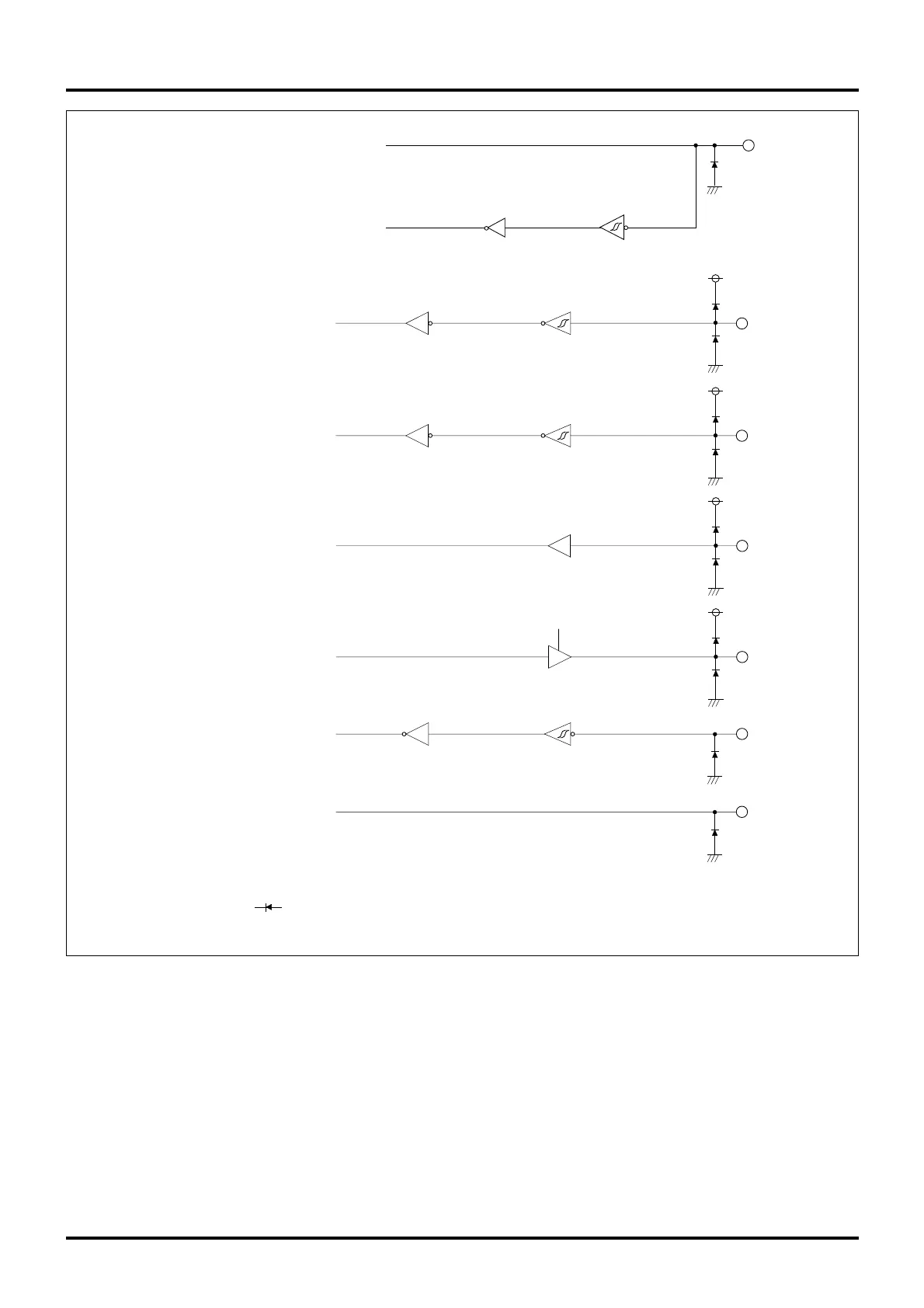
Notes: • The circle denotes a pin.
• The symbol denotes a parasitic diode. Make sure the voltage applied to each pin does not exceed
the VCCE voltage.
8.5 Port Peripheral Circuits
Figure 8.5.4 Port Peripheral Circuit Diagram (4)

 Loading...


