10
10-5
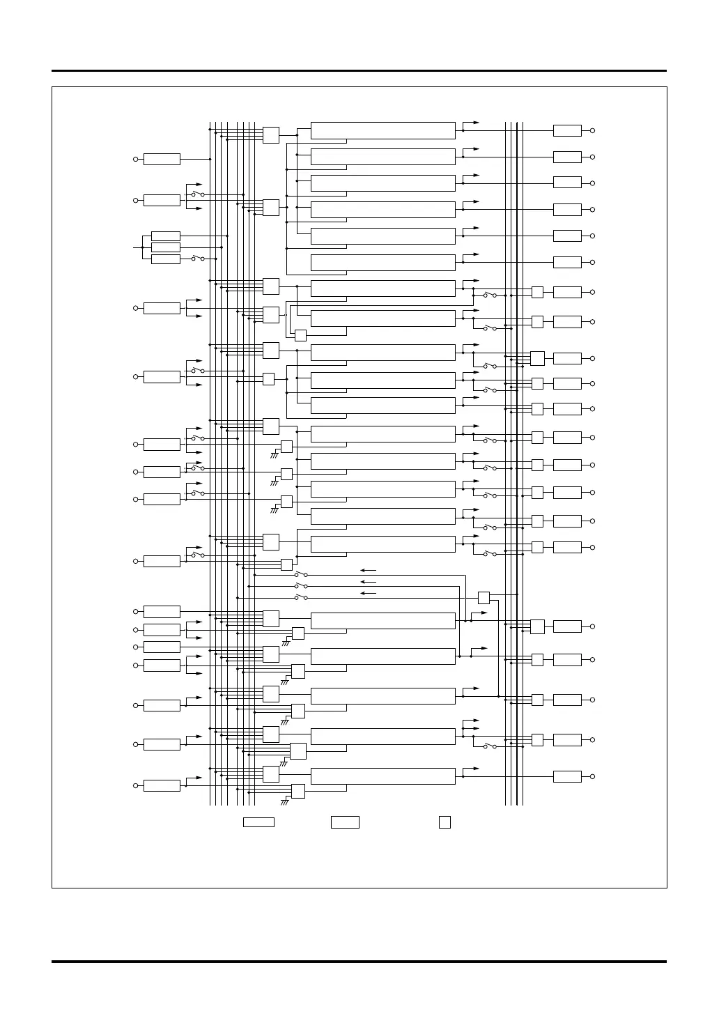
MULTIJUNCTION TIMERS
10.1 Outline of Multijunction Timers
32180 Group User’s Manual (Rev.1.0)
Figure 10.1.1 Block Diagram of MJT (1/4)
TCLK0 (P124)
TIN0 (P150)
BCLK/2
TIN1 (P151)
TIN2 (P152)
TIN3 (P153)
TIN4 (P154)
TIN5 (P155)
TIN6 (P156)
TCLK1 (P125)
TIN7 (P157)
TCLK2 (P126)
TIN8 (P140)
TIN9 (P141)
TIN10 (P142)
TIN11 (P143)
TO0 (P110)
TO1 (P111)
TO2 (P112)
TO3 (P113)
TO4 (P114)
TO5 (P115)
TO6 (P116)
TO7 (P117)
TO8 (P100)
TO9 (P101)
TO10 (P102)
TO11 (P103)
TO12 (P104)
TO13 (P105)
TO14 (P106)
TO15 (P107)
TO16 (P93)
TO17 (P94)
TO18 (P95)
TO19 (P96)
TO20 (P97)
IRQ9
DMA3,DMA commom
IRQ9
DMA6
IRQ9
DMA7
IRQ12
DMA1
IRQ12
IRQ12
IRQ12
IRQ8
DMA8
IRQ8
DMA9
IRQ8
IRQ8
IRQ8
IRQ2
IRQ2
IRQ2
IRQ2
IRQ2
IRQ2
IRQ1
IRQ1
IRQ6
IRQ6
IRQ5
IRQ0
IRQ0
IRQ0
IRQ0
IRQ4
IRQ4
IRQ4
IRQ4
DMA0
DMA
common
IRQ3
IRQ3
: Prescalers
: Output flip-flop
: Selector
SF/F
PRS0–5
TOP 0
clk
en
udf
TOP 1
clk
en
udf
TOP 2
clk
en
udf
TOP 3
clk
en
udf
TOP 4
clk
en
udf
TOP 5
clk
en
udf
TOP 6
clk
en
udf
TOP 7
clk
en
udf
TOP 8
clk
en
udf
TOP 9
clk
en
udf
TOP 10
clk
en
udf
TIO 0
clk
en/cap
udf
TIO 1
clk
en/cap
udf
TIO 2
clk
en/cap
udf
TIO 3
clk
en/cap
udf
TIO 4
clk
en/cap
udf
TIO 5
clk
en/cap
udf
TIO 6
clk
en/cap
udf
TIO 7
clk
en/cap
udf
TIO 8
clk
en/cap
udf
TIO 9
clk
en/cap
udf
S
S
S
S
S
S
S
S
S
S
S
S
S
S
S
S
S
S
S
S
S
S
S
S
S
S
S
S
S
S
S
S
TIN0S
TCLK0S
F/F10
F/F11
F/F12
F/F13
F/F14
F/F15
F/F16
F/F17
F/F18
F/F19
F/F20
F/F0
F/F1
F/F2
F/F3
F/F4
F/F5
F/F6
F/F7
F/F8
F/F9
TIN1S
TIN2S
TIN3S
TIN4S
TIN5S
TIN6S
S
S
S
PRS0
PRS1
PRS2
TCLK1S
TIN7S
TCLK2S
TIN8S
TIN9S
TIN10S
TIN11S
S
S
S
3210 3210 0123
3210 3210 0123
Clock bus Input event bus Output event bus
Notes: • IRQ0-18 denotes interrupt signals, of which the same number represents the same group of interrupts.
• DMA0-9 and DMA common denote DMA request signals to the DMAC.
• AD0TRGa and AD1TRG denote trigger signals to the A-D0 and A-D1 converters, respectively.

 Loading...


