10
10-27
MULTIJUNCTION TIMERS
10.2 Common Units of Multijunction Timers
32180 Group User’s Manual (Rev.1.0)
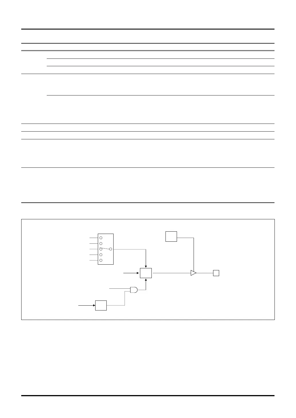
Output event bus 0
Data bus
F/F protect (FPn)
WR
Data bus
Output control (ON/OFF)
TOn
Internal edge signal
Port operation mode register (PnMOD)
F/Fn output data (FDn)
TOP/TIO/TOU udf
F/F source selection (FSn)
Output event bus 1
Output event bus 2
Output event bus 3
F/F
F/F
F/F
Figure 10.2.2 Configuration of the F/F Output Circuit
Table 10.2.5 Timing at Which Signals Are Generated to the Output Flip-Flop by Each Timer
Timer Mode Timing at which signals are generated to the output flip-flop
TOP Single-shot output mode When count is enabled or underflows
Delayed single-shot output mode When counter underflows
Continuous output mode When count is enabled or underflows
TIO Measure clear input mode When counter underflows
Measure free-run input mode When counter underflows
Noise processing input mode When counter underflows
PWM output mode When count is enabled or underflows
Single-shot output mode When count is enabled or underflows
Delayed single-shot output mode When counter underflows
Continuous output mode When count is enabled or underflows
TMS (16-bit measure input) No signals generated
TML (32-bit measure input) No signals generated
TID Fixed period count mode No signals generated
Event count mode No signals generated
Multiply-by-4 event count mode No signals generated
Up/down event count mode No signals generated
TOU PWM output mode When count is enabled or underflows
Single-shot PWM output mode When counter underflows
Delayed single-shot output mode When counter underflows
Single-shot output mode When count is enabled or underflows
Continuous output mode When count is enabled or underflows

 Loading...


