16
16-2
WAIT CONTROLLER
32180 Group User’s Manual (Rev.1.0)
16.1 Outline of the Wait Controller
The Wait Controller controls the number of wait states inserted in bus cycles when accessing an extended exter-
nal area. The Wait Controller is outlined in the table below.
Table 16.1.1 Outline of the Wait Controller
Item Description
Target space Control is applied to the following address spaces depending on operation mode:
Single-chip mode: No target space (Settings of the Wait Controller have no effect)
External extension mode
:
CS0 area (1 Mbytes), CS1 area (2 Mbytes),
CS2 area (2 Mbytes), CS3 area (2 Mbytes)
Processor mode: CS0 area (2 Mbytes), CS1 area (2 Mbytes),
CS2 area (2 Mbytes), CS3 area (2 Mbytes)
Number of wait states that can be inserted
0–7 wait states set by software + any number of wait states set from the WAIT# pin
* One wait state is equivalent to one BCLK cycle.
During external extension and processor modes, four chip select signals (CS0# to CS3#) are output, each corre-
sponding to one of the four extended external areas referred to as CS0 through CS3.
16.1 Outline of the Wait Controller
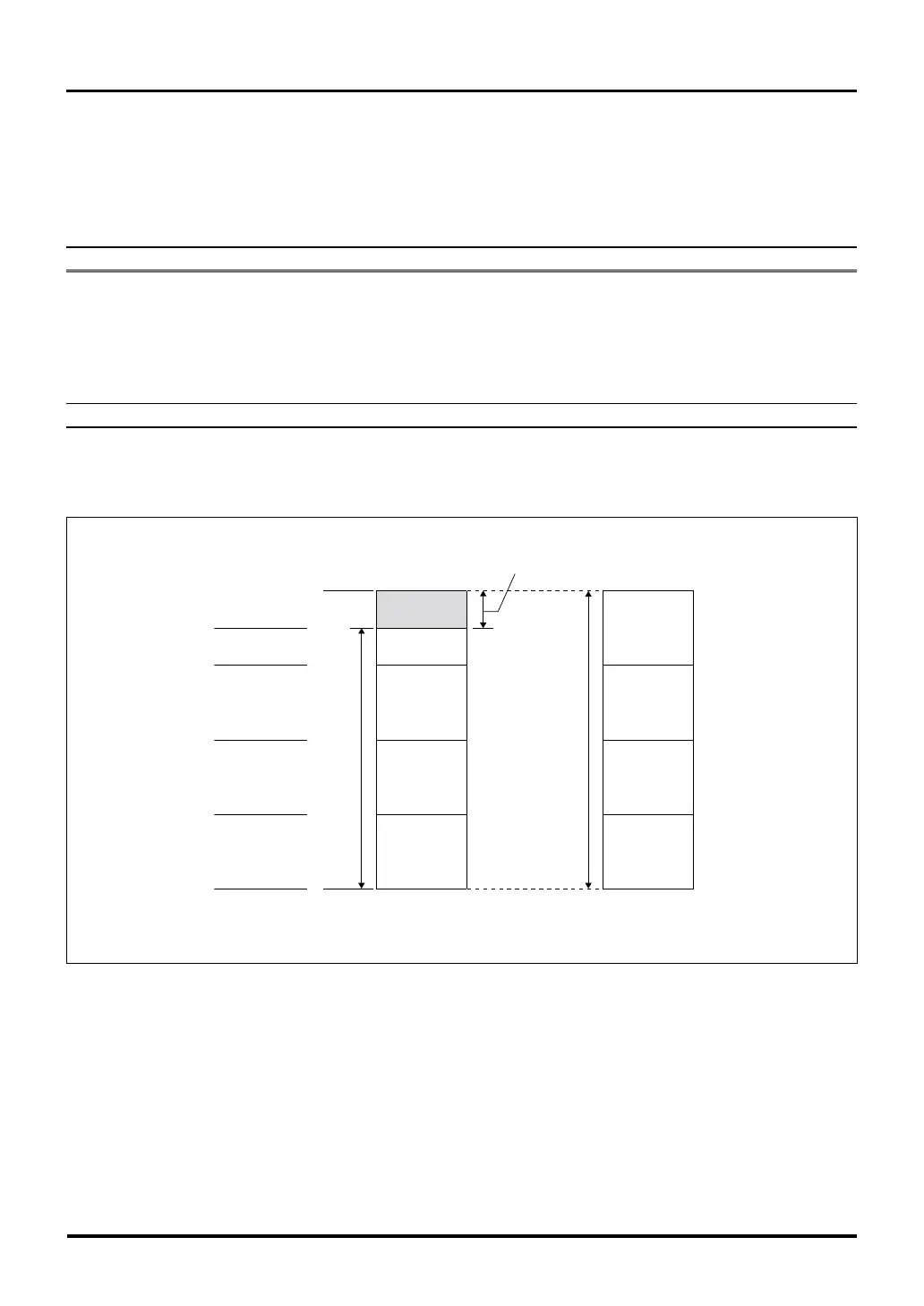
H'0000 0000
H'0010 0000
H'000F FFFF
H'0020 0000
H'001F FFFF
H'0040 0000
H'003F FFFF
H'0060 0000
H'005F FFFF
H'007F FFFF
Internal ROM area
CS0 area
CS1 area
CS2 area
CS3 area
CS0 area
(2MB)
CS1 area
(2MB)
CS2 area
(2MB)
CS3 area
(2MB)
Extended external area
Extended external area
Non-CS0 area
(Internal ROM access area)
<External extension mode> <Processor mode>
Figure 16.1.1 CS0–CS3 Area Address Map
When accessing the extended external area, the Wait Controller controls the number of wait states inserted in bus
cycles based on the number of wait states set by software and those entered from the WAIT# pin.
The number of wait states that can be controlled in software is 0 to 7.
When the input signal on the WAIT# pin is sampled low in the last cycle of internal wait state, the wait state is
extended as long as the WAIT# input signal is held low. Then when the WAIT# input signal is released back high,
the wait state is terminated and the next new bus cycle is entered into.

 Loading...


