Appendix 4
Appendix 4-7
32180 Group User's Manual (Rev. 1.0)
SUMMARY OF PRECAUTIONS
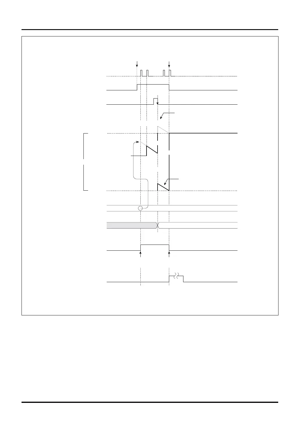
Figure 4.8.1 Example of an Operation in TOP Single-shot Output Mode Where Count Overflows Due to Correction
Appendix 4.8 Precautions about the Multijunction Timers
H'FFFF
H'0000
H'FFF8
H'(FFF0+0014)
H'0004
H'FFF0
H'0014
H'FFF8
H'FFFF
Data inverted
by enable
Data inverted
by underflow
H'(FFF8-1)
Counter
Count clock
Correction register
F/F output
TOP interrupt request
due to underflow
Enable bit
Note: • This diagram does not show detailed timing information.
Reload register
Write to the
correction register
Enabled
(by writing to the enable bit
or by external input)
Disabled
(by underflow)
Indeterminate
value
Actual count after overflow
Overflow occurs
Indeterminate
 Loading...


