1.5 Connectors and their Pinouts
All of VersaSync's connectors are provided at the front panel of the unit, below
the Status LEDs. The Advanced Military Connectors are keyed for foolproof con-
nectivity and offer a push-pull locking mechanism. Since the connectors are
keyed, you should not need to force connectivity. Inspect all connectors and
cables for damage prior to connection.
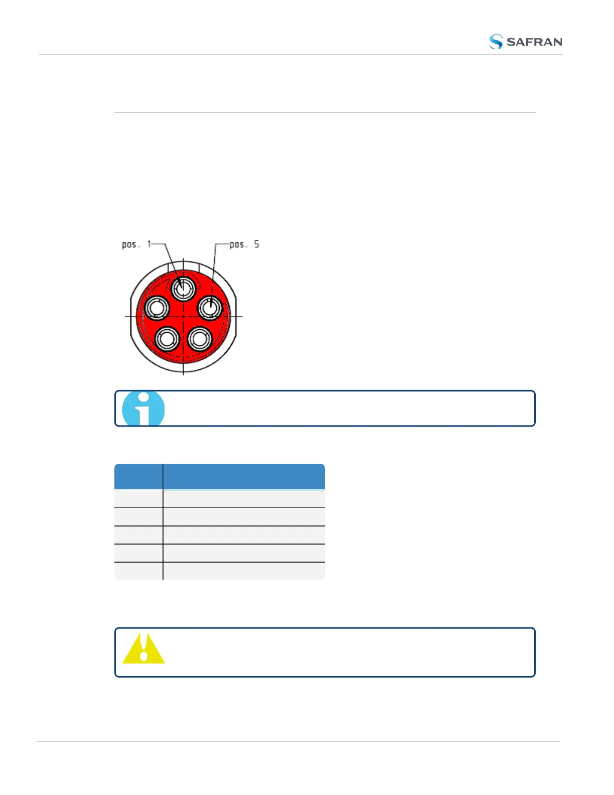
1.5.1 Power Connector
Note: View in mating direction from front.
Table 1-5:
Power connector pinout
Pin Signal
1 V
Main
(10 to 32V)
2 -not used-
3 V
Standby
(10 to 32 V)
4 GND (to Standby)
5 GND (to Main)
This product is designed to handle a maximum voltage of up to 32 V
DC
. Power
supplies with higher voltage or transient/ cranking power will require a power
conditioner or surge blocker.
Caution: Reversed polarity can blow an internal fuse that protects
the product from damage. Use care when building power cables.
10
CHAPTER 1 • VersaSync User Manual Rev. 12
1.5 Connectors and their Pinouts