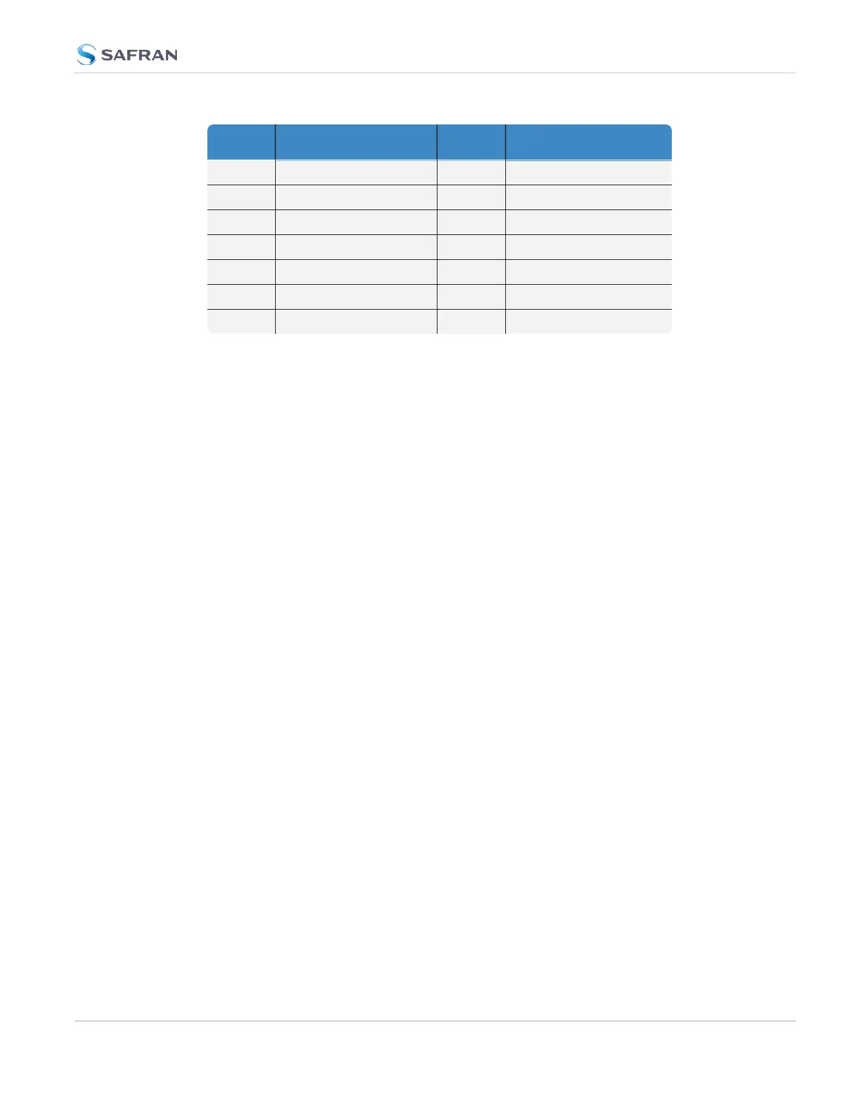
Pin Signal Pin Signal
2 Ethernet_1 A– 10 Ethernet_2 A–
3 Ethernet_1 B+ 11 Ethernet_2 B+
4 Ethernet_1 B– 12 Ethernet_2 B–
5 Ethernet_1 C+ 13 Ethernet_2 C+
6 Ethernet_1 C– 14 Ethernet_2 C–
7 Ethernet_1 D+ 15 Ethernet_2 D+
8 Ethernet_1 D– 16 Ethernet_2 D–
It is also possible to wire your connector to 100MbE, using only 4 wires. Contact
Tech Support for more information.
The pinouts described above are from the hardware design. They correspond
with the software naming convention of interfaces as follows: Ethernet_ 1 is
referred to as "eth0" in the system and Web UI, and Ethernet_2 is referred to as
"eth1".
1.5.4 Optional I/O Connector
The Optional I/O connector ("SAASM" or "FILL/Z") is used in conjunction with
the Option Board that is available for VersaSync. If the unit is not equipped with
an Option Board, this connector is not used.
1.5.5 Coaxial Connectors
VersaSync offers five (5) coaxial connectors. Standard configuration includes the
GNSS antenna input connector and (4) 10MHz sinewave outputs. (Certain mod-
els may have variation on this setup. Refer to your purchase order for information
on your VersaSync model.)
The coaxial connectors (aside from the GNSS connection) produce a 10MHz out-
put that can be simultaneously disabled through the Web UI.
All coaxial connectors are standard SMA connectors (recommended torque
value: 8-10 in-lbs).
Mating Connector Plugs
The table below lists the part numbers for the mating connectors. The con-
nectors can be ordered through Orolia or ODU-USA Inc. All connectors are cir-
cular ODU AMC
®
"mil-type" connectors.
1.5 Connectors and their Pinouts
CHAPTER 1 • VersaSync User Manual Rev. 12
13