2.7.1.1 Signal Types
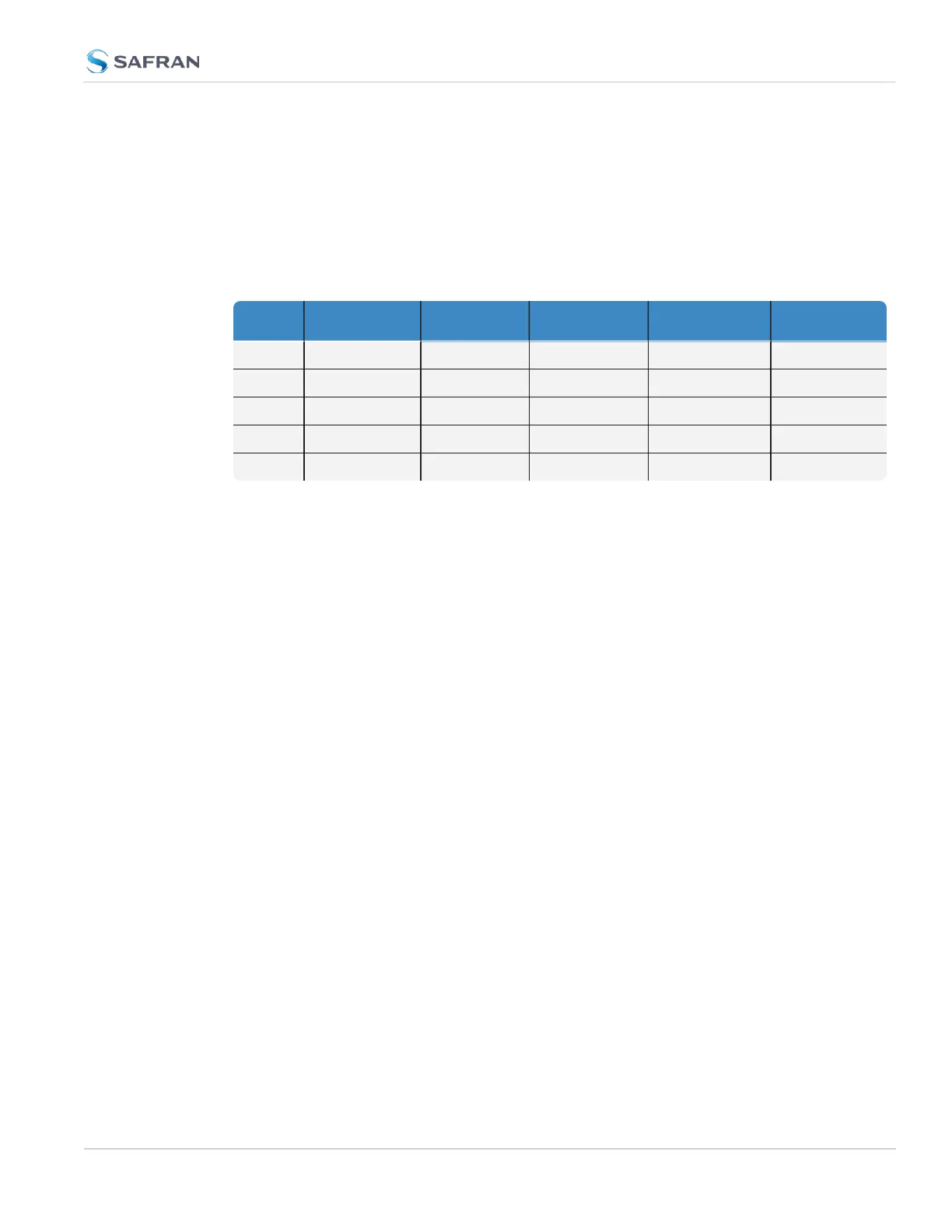
The table below shows the maximum number of available interfaces for each sig-
nal type. Note that you can assign only one signal for each pin pair, hence only
four to nine input and output signals can be transmitted/received at any given
time. For details, see the signal mapping table below.
Table 2-2:
Available signal types
DCLS, TTL DCLS, 10V RS485 RS 485, 120 Ω RS232
PPS out (5), in (2) out (1), in (1) out (4), in (4) in (4)
IRIG out (5), in (2) out (1), in (1) out (4), in (4) in (4)
HQ out (5), in (2) out (1), in (1) out (4), in (4) in (4)
GPIO out (5) out (1)
ASCII out (4), in (4) in (4) out (3), in (3)
Note: ASCII Time Code is abbreviated in the UI as ATC.
DCLS Signal Lines
Up to six TTL (5V) or 10V DCLS outputs and three DCLS inputs are available for
e.g., 1PPS, xPPS, IRIG, HaveQuick, ASCII ToD signal transmission.
Single-ended Serial Lines
VersaSync provides up to 3 RX and 3 TX RS232 interfaces for e.g., ASCII ToD –
NMEA 0183 (ICD-GPS-153).
Differential Serial Lines
Up to four differential serial lines are available. Each of them can be set to RS485
electrical standard, and used as input or output. PPS or Time-of-Day messages
are available, as well as HAVE QUICK and other formats. Note that this kind of
interface uses two Channels.
Non-Configurable Pins
Channel # 0 provides a DCLSTTL output signal that is not user-configurable.
Also note that pins # 19 through 26 are reserved for the USB command line inter-
face.
2.7.1.2 I/O Signal Mapping Table
Each Channel (i.e., each pin pair e.g., "3&4" = Channel 1) can serve as only one
interface, and not all combinations are possible due to the internal multiplexer
2.7 Configuring Inputs/Outputs
CHAPTER 2 • VersaSync User Manual Rev. 12
45