architecture.
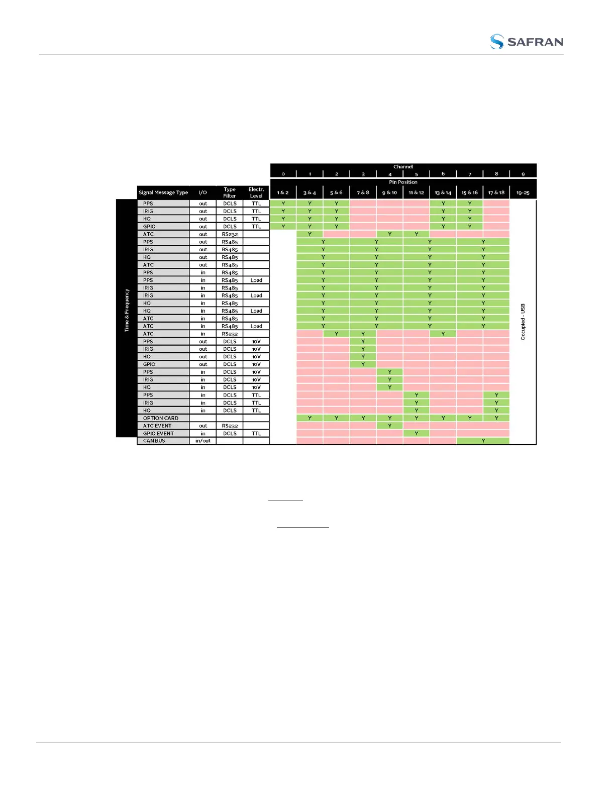
The table below illustrates the signal combinations that can be assigned to the 18
configurable pins.
Table 2-3:
I/O signal mapping to Channels
Notes:
Pins to Channels (e.g., pins 3 & 4= Channel 1)
green = Signal Message Type can be assigned to this Channel (RS485 requires
two Channels)
red = This Signal Message type cannot be assigned to this Channel
ATC = ASCII Time Code
Configuring a new Input or Output
1. In the VersaSync Web UI, navigate to MANAGEMENT > NETWORK: Pin Lay-
out. The Pin Layout screen will be displayed.
2. Prior to assigning the new output, identify a pin pair in the pin Layout table
that is not used (Signal = "None") or not needed. You can Delete it, but you
may also simply assign the new PPS Output as described below, thus over-
writing the existing Input or Output.
46
CHAPTER 2 • VersaSync User Manual Rev. 12
2.7 Configuring Inputs/Outputs