Test any new cables to safely power the unit before connecting your VersaSync
to any other inputs or outputs (such as a GNSS antenna), and before grounding
your unit to a vehicle.
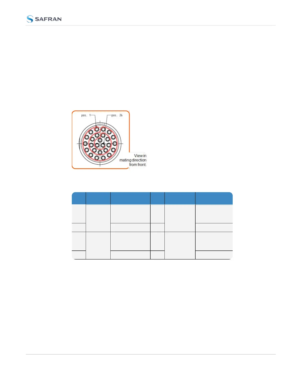
1.5.2 Input/Output Connector
VersaSync has a 26- pin input/output connector that offers 8 software- con-
figurable CHANNELS, plus one fixed DCLS channel, and a USB interface. To learn
more about types of interfaces and signals, and how to configure them, see
"Assigning I/O Pins" on page44.
Table 1-6:
Default I/O connector pinout
Pin Channel Signal Pin Channel Signal
1
0 1PPS output (5V)
15
7 Have Quick out-
put (RS-485 sig-
nal +)
2
GND
16
GND
3
1 HaveQuick input
(RS-485 signal
+)
17
8 Have Quick out-
put (RS-485 sig-
nal –)
4
GND
18
GND
1.5 Connectors and their Pinouts
CHAPTER 1 • VersaSync User Manual Rev. 12
11