First, assign a GPIOoutput to an I/O pin pair:
1. In the Web UI, navigate to MANAGEMENT > NETWORK: Pin Layout. The
Pin Layout screen will be displayed.
2. Prior to assigning the new output, identify a pin pair in the Pin Layout table
that is not used (Signal = "None") or not needed. You can Delete it, but you
may also simply assign the new PPS Output as described below, thus over-
writing the existing Input or Output.
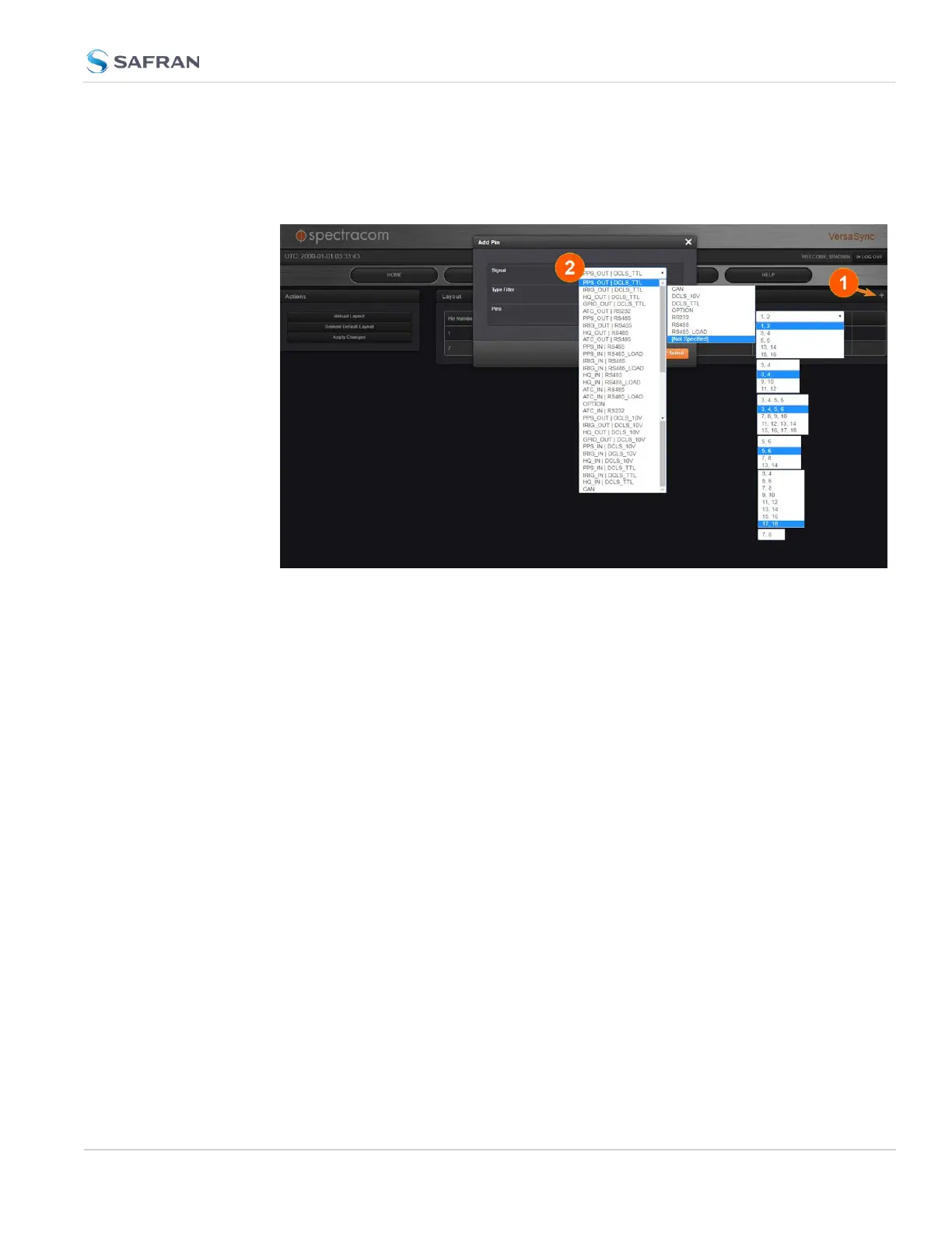
3. Add a pin configuration by clicking the PLUS icon in the top-right corner
(1). The Add Pin window will display.
4. Start with the Type Filter drop-down menu (second line in the window) and
select DCLS_TTL.
5. From the Signal drop-down menu, select GPIO_OUT DCLS_TTL.
6. From the Pins drop-down menu in line 3, select e.g., pins 1,2.
7. Click Submit.
8. In the Actions panel, click Apply Changes.
Then, configure the settings for the newly created output:
9. Navigate to INTERFACES > OUTPUTS > General Purpose Output/GP Out-
put 0. The GPOutput 0 status window will be displayed.
10. Click Edit. The GPOutput 0 configuration window will be displayed.
11. Under General, set the Output Mode to Square Wave, and check Output
Enabled.
2.7 Configuring Inputs/Outputs
CHAPTER 2 • VersaSync User Manual Rev. 12
51