ENGINE GENERAL INFORMATION AND DIAGNOSIS (M13 ENGINE) 6-2-37
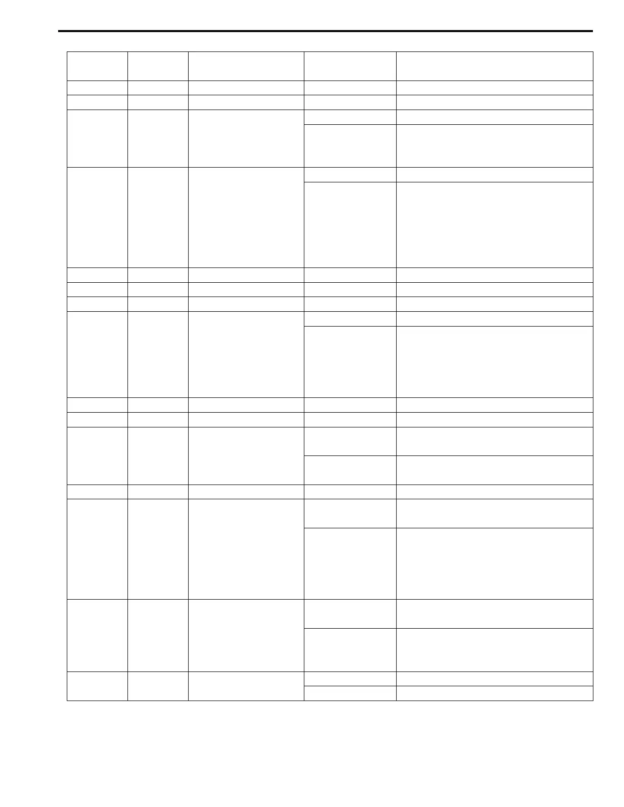
TERMINAL
NUMBER
WIRE
COLOR
CIRCUIT
NORMAL
VOLTAGE
CONDITION
E23-1 BLK/YEL Ground for ECM Below 0.3 V Ignition switch turned ON
E23-2 BLK/YEL Ground for ECM Below 0.3 V Ignition switch turned ON
E23-3 BLU/RED
Heater output of
heated oxygen sen-
sor–2
10 – 14 V Ignition switch turned ON
0 – 1 V
(Reference wave-
form No.1)
Engine running at idling after vehicle
running over 30 km/h, 19ml/h for 5 min.
E23-4 YEL
Heater output of
heated oxygen sen-
sor–1
10 – 14 V Ignition switch turned ON
*0 – 2 V
↑↓
13.5 –14.8 V
(Reference wave-
form No.2 and
No.3)
Engine running at idling with after warm-
ing up.
(Output signal is active low duty pulse.
Duty ratio varies depending on engine
condition.)
E23-5 –– – –
E23-6 –– – –
E23-7 –– – –
E23-8 GRN/YEL IAC valve output
0 – 1 V Ignition switch turned ON
*0 – 2 V
↑↓
8 – 14 V
(Reference wave-
form No.4)
Engine running at idling with after warm-
ing up.
(Output signal is active low duty pulse.
Pulse generated times depending on
vehicle condition)
E23-9 –– – –
E23-10 –– – –
E23-11 ORN
A/C compressor relay
output (if equipped)
10 – 14 V
Engine running, A/C request signal high
input
0 – 1 V
Engine running, A/C request signal low
input
E23-12 –– – –
E23-13 RED/BLK
EVAP canister purge
valve output
10 – 14 V
Ignition switch turned ON with engine
stop
*0 – 0.6 V
↑↓
10 – 14 V
(Reference wave-
form No.25)
Engine running and vehicle running over
40 km/h, 25 ml/h
(Output signal is 10 Hz duty pulse. Duty
ratio varies depending on vehicle condi-
tion.)
E23-14 GRN Fuel pump relay output
0 – 2.5 V
For 3 sec. from the time is ignition switch
turned to ON or while engine is running
10 – 14 V
On and after 3 sec. from the time is igni-
tion switch turned to ON or while engine
is stop
E23-15 BLU/BLK
Main power supply
relay output
10 – 14 V Ignition switch is turned OFF
0 – 2 V Ignition switch is turned ON