6-2-144 ENGINE GENERAL INFORMATION AND DIAGNOSIS (M13 ENGINE)
DTC P1510 ECM Back-up Power Supply Malfunction
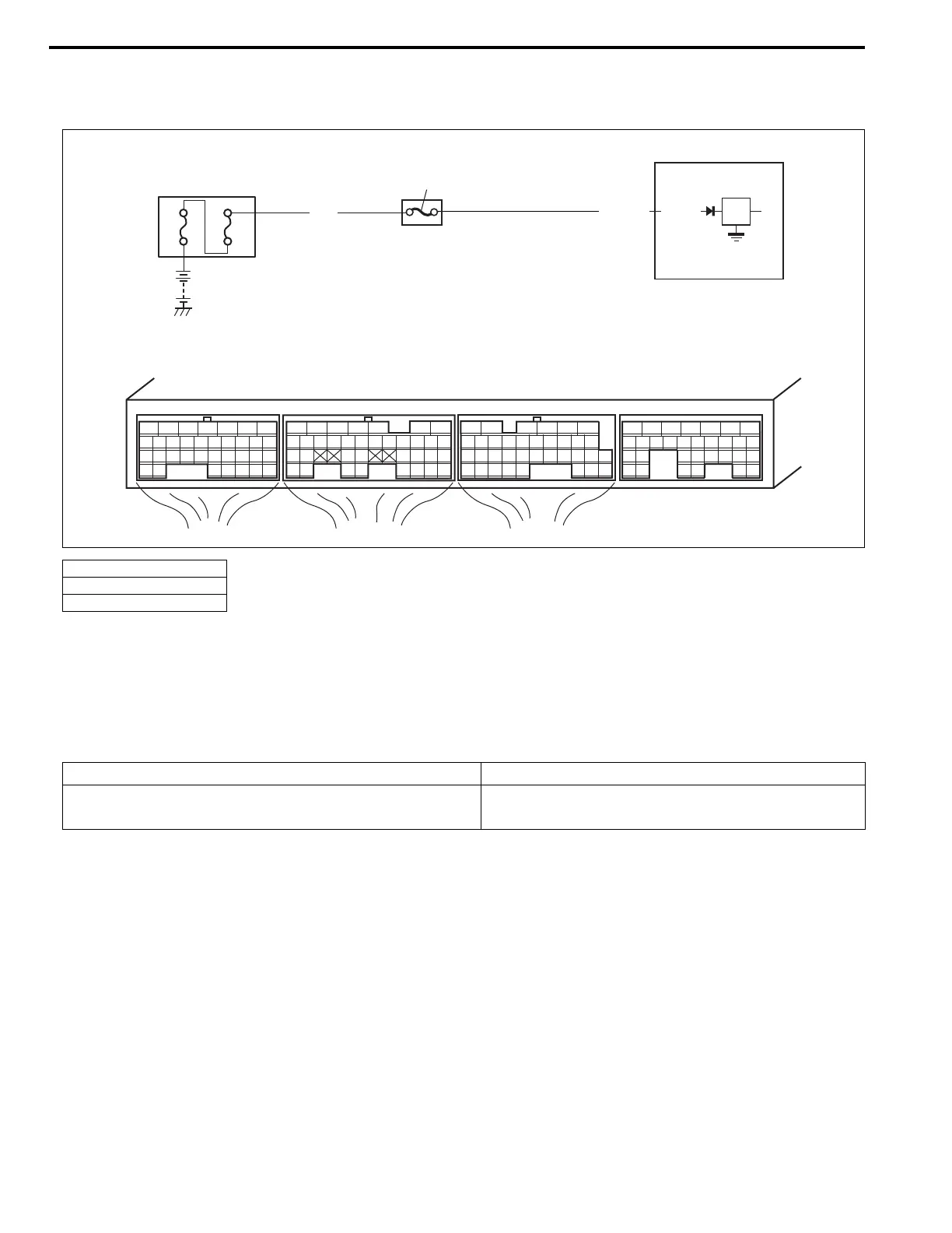
Wiring Diagram
Circuit Description
Battery voltage is supplied so that diagnostic trouble code memory, values for engine control learned by ECM,
etc. are kept in ECM even when the ignition switch is turned OFF.
DTC Detecting Condition and Trouble Area
DTC Confirmation Procedure
1) Connect scan tool to DLC with ignition switch turned OFF.
2) Turn ON ignition switch and clear DTC using scan tool and run engine at idle speed for 1 min.
3) Check DTC and pending DTC.
1. ECM
2. “DOME RADIO” fuse
3. Relay box
E23 E22 E21
12345671234561234567
7
891011121314151617 8910111213141516 891011121314151617
1819
1819
1718192021222324252627 20212223 202122232425 24252627 2627
2829303132 32 282930 28293031 3133 33 323334 3435 3435
WHT/BLU
80A
60A
WHT
E21-16
3
2
1
DTC Detecting Condition Trouble Area
Back-up circuit voltage is less than specified value for 5
seconds continuously while engine running.
Battery voltage supply circuit