ENGINE GENERAL INFORMATION AND DIAGNOSIS (M13 ENGINE) 6-2-161
Table B-6 Electric Load Signal Circuit Check
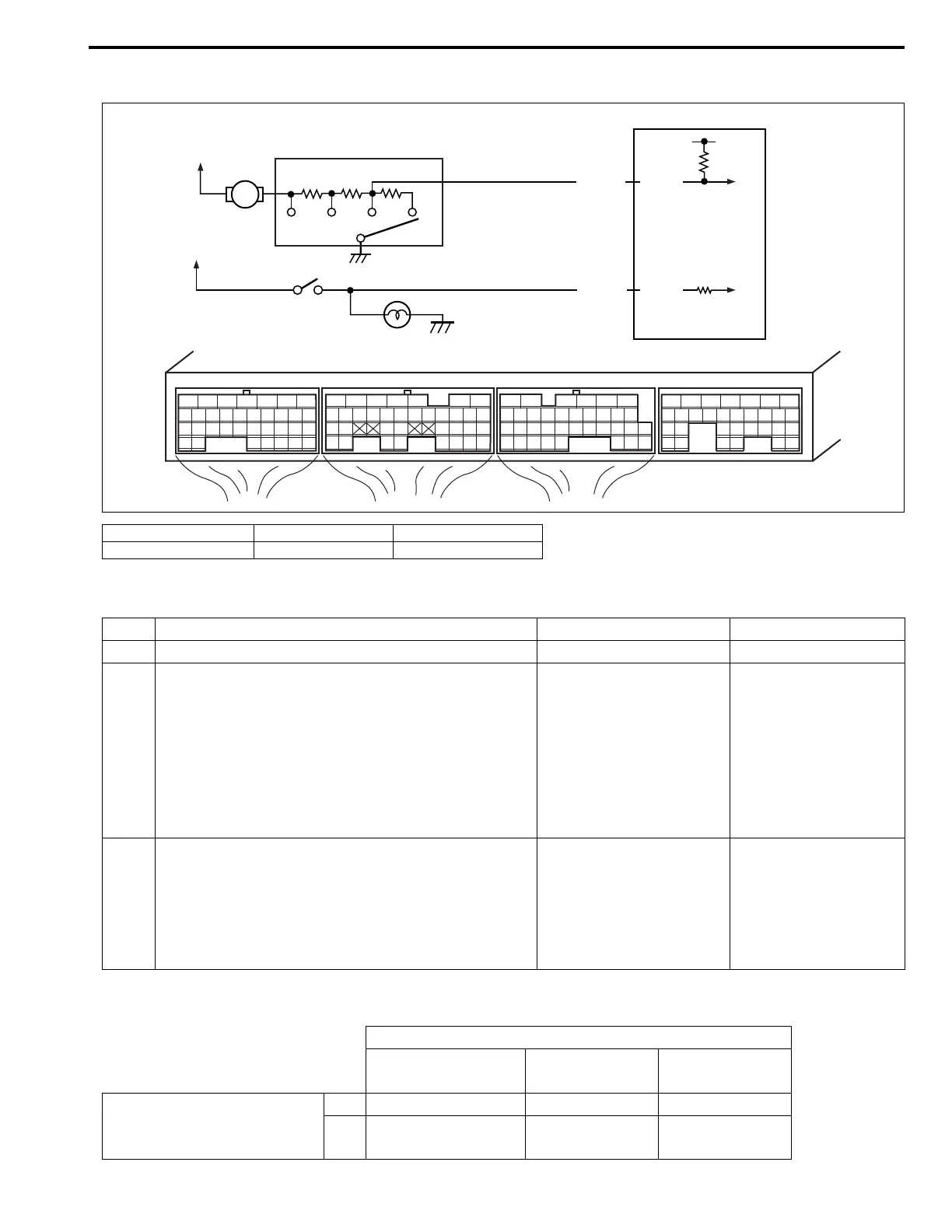
Troubleshooting
Table 1 for Step 2 and 3
1. Blower fan motor 3. Position lamp 5. To “HEATER” fuse
2. Blower fan switch 4. ECM 6. To “TA I L” fuse
PNK/BLU
RED/YEL
E21-13
E21-33
E23 E22 E21
12345671234561234567
7
891011121314151617 8910111213141516 891011121314151617
1819
1819
1718192021222324252627 20212223 202122232425 24252627 2627
2829303132 32 282930 28293031 3133 33 323334 3435 3435
5
6
1
3
2
4
Step Action Yes No
1 Do you have SUZUKI scan tool? Go to Step 2. Go to Step 3.
2 Check electric load signal circuit.
1) Connect SUZUKI scan tool to DLC with ignition
switch OFF.
2) Start engine and select “DATA LIST” mode on
scan tool.
3) Check electric load signal under following each
condition. See Table 1.
Is check result satisfactory?
Electric load signal circuit
is in good condition.
“PNK/BLU” and/or
“RED/YEL” circuit open
or short, electric load
diodes malfunction or
each electric load cir-
cuit malfunction.
3 Check electric load signal circuit.
1) Turn ignition switch ON.
2) Check voltage at each terminals “E21-13” and
“E21-33” of ECM connector connected, under
above each condition. See Table 1.
Is each voltage as specified?
Electric load signal circuit
is in good condition.
“PNK/BLU” and/or
“RED/YEL” circuit open
or short, electric load
diodes malfunction or
each electric load cir-
cuit malfunction.
Scan tool or voltmeter
SUZUKI
SCAN TOOL
VOLTAGE
AT E2 1- 33
VOLTAGE
AT E2 1- 13
Ignition switch ON, Small
light and heater blower fan all
turned
OFF OFF 0 V 10 – 14 V
ON ON 10 – 14 V 0 V