6-2-158 ENGINE GENERAL INFORMATION AND DIAGNOSIS (M13 ENGINE)
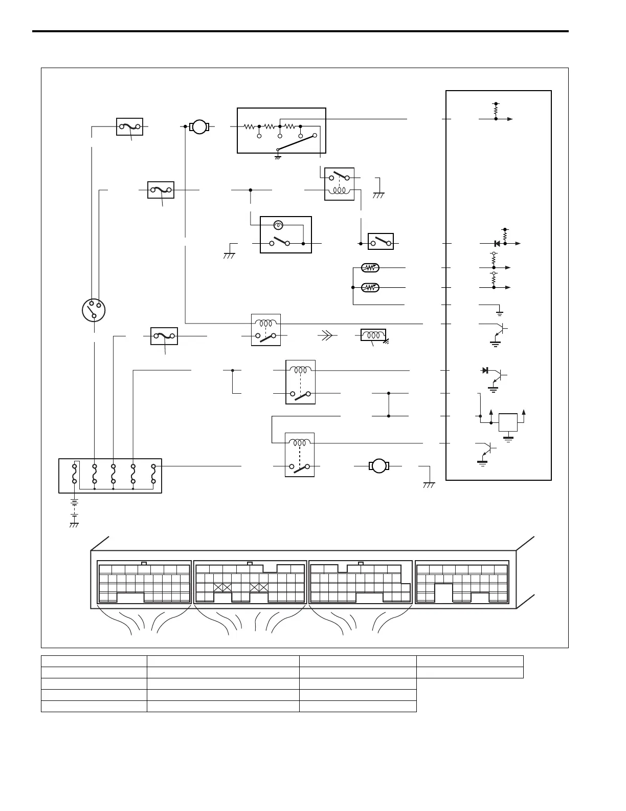
Table B-5 A/C Signal Circuits Check (Vehicle with A/C)
1. Blower fan motor 6. Compressor relay 11. ECM 16. “IG COIL” fuse
2. Blower fan switch 7. A/C compressor 12. Ignition switch 17. “A/C” fuse
3. A/C switch 8. Radiator fan motor relay 13. ECT sensor
4. A/C pressure switch 9. Radiator fan motor 14. Evaporator thermistor
5. Blower motor relay 10. Main relay 15. “HEATER” fuse
BRN/WHT
GRN/RED
WHT/BLU
YEL
PNK/BLU
BLU/YEL RED
60A
60A
20A 30A
E21-13
E21-15
E22-28
E23 E22 E21
12345671234561234567
7
891011121314151617 8910111213141516 891011121314151617
1819
1819
1718192021222324252627 20212223 202122232425 24252627 2627
2829303132 32 282930 28293031 3133 33 323334 3435 3435
YEL/GRN
GRN/ORN
GRN/ORN
E21-16
E21-30
LT GRN/RED
ORN
E23-11
GRN
BLK
BLK
PNK
WHT
BLK/YELBLU/WHT
BLK/WHTBLK/WHTBLU/BLK
BLK/WHT
BLU/YEL
E23-15
12V
5V
E21-6
E21-5
BLK/REDBLK/RED
BLK/RED
BLK/YEL BLK/YEL
BLK/YEL
BLU/BLK
BLK/YEL BLU/RED BLK
BLU
E21-4
BLK/RED
80A
15
2
1
5
4
16
12
17
6
10
13
14
8
9
7
11
3