6-2-136 ENGINE GENERAL INFORMATION AND DIAGNOSIS (M13 ENGINE)
DTC P1500 Starter Signal Circuit Malfunction
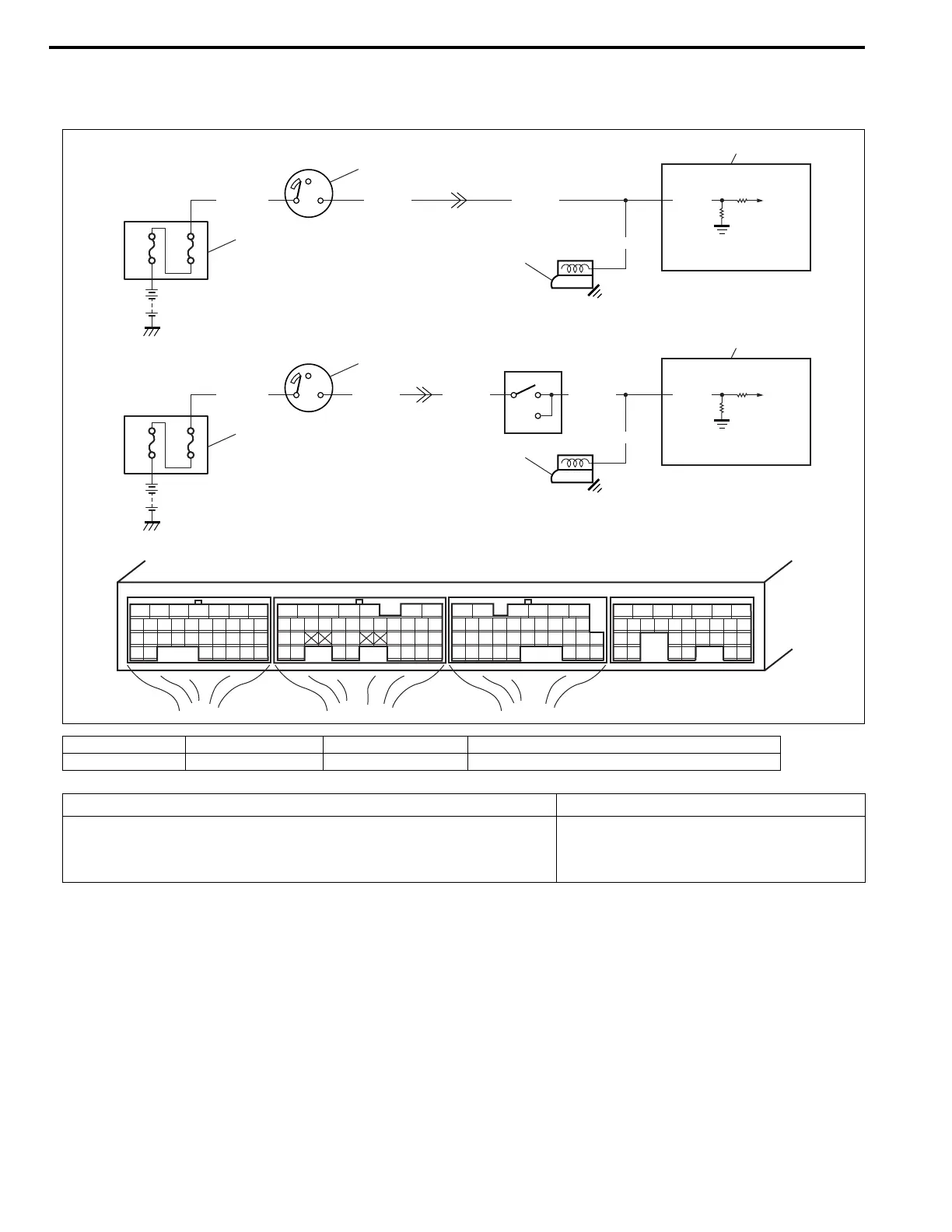
Wiring Diagram
DTC Confirmation Procedure
1) With ignition switch turned OFF, connect scan tool.
2) Turn ON ignition switch and clear DTC using scan tool.
3) Start engine and run it at idle for 3 min. or more.
4) Check DTC and pending DTC.
[A]: M/T Vehicle 1. ECM 3. Ignition switch 5. Instrument panel harness/engine harness connector
[B]: A/T Vehicle 2. Starter motor 4. Relay box 6. Transmission range sensor (shift switch)
E22-35
WHT/BLU
80A
60A
BLK/YELBLK/YEL
1
2
3
5
4
C64 C63 G91
12345671234561234567
7
891011121314151617 8910111213141516 891011121314151617
1819
1819
1718192021222324252627 20212223 202122232425 24252627 2627
2829303132 32 282930 28293031 3133 33 323334 3435 3435
BLK/YEL
E22-35
WHT/BLU
80A
60A
BLK/RED
BLK/YELBLK/YEL
1
2
3
5
4
BLK/YEL
P
N
[A]
[B]
6
DTC Detecting Condition Trouble Area
• Low voltage at terminal “E22-35” when cranking engine
• High voltage at terminal “E22-35” after starting engine
(2 driving cycle detection logic)
• Engine starter signal circuit
• ECM