AUTOMATIC TRANSAXLE (M13 ENGINE) 7B1-87
Inspection of TCM and Its Circuits
TCM and its circuits can be checked at TCM wiring connectors by
measuring voltage and resistance.
Inspection
1) Remove TCM (1) from vehicle referring to “Transmission
Control Module” in this section.
2) Connect TCM connectors (2) to TCM.
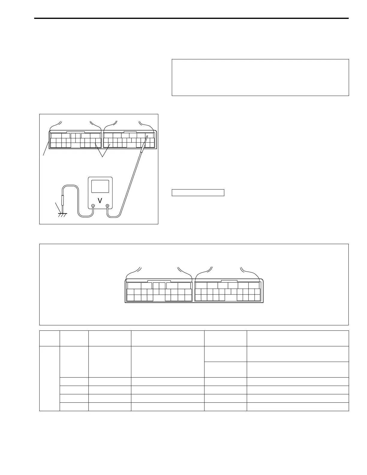
3) Check voltage at each terminal of connectors connected.
Terminal Arrangement of TCM Coupler (Viewed From Harness Side)
CAUTION:
TCM cannot be checked by itself, it is strictly prohibited
to connect voltmeter or ohmmeter to TCM with connector
disconnected from it.
NOTE:
As each terminal voltage is affected by battery voltage,
confirm that it is 11 V or more when ignition switch is ON.
3. Body ground
1
2
3
65
16 15 14 13 12 11
43
24 23 2122
10 9 8 7
21
1920 18 17
E13
17 16
26 25
15 14
65 342
13 12
23 2224
11 10 9
21 20 19
87
18
1
E12
Con-
nector
Te r mi nal
number
Wire color Circuit
Normal
Voltage
Condition
E12
1RED
Transmission range sen-
sor (“R” range)
8 – 14 V
Ignition switch ON, selector lever at
“R” range
0 – 1 V
Ignition switch ON, selector lever at
other than “R” range
2 ––– –
3 ––– –
4 ––– –
5 ––– –