6-2-162 ENGINE GENERAL INFORMATION AND DIAGNOSIS (M13 ENGINE)
Table B-7 Radiator Fan Control System Check
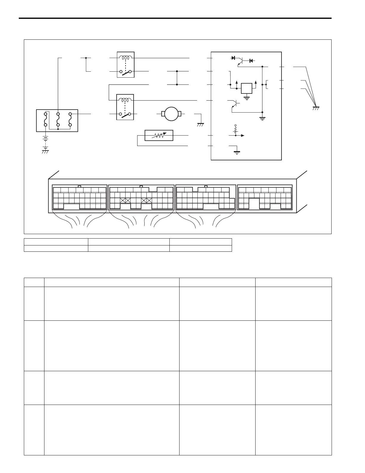
Troubleshooting
1. Relay box 3. Radiator fan relay 5. ECT sensor
2. Main relay 4. Radiator fan motor 6. ECM
E23-15
12V
5V
E21-6
E21-5
BLK/REDBLK/RED
BLK/RED
80A
BLK/YEL BLK/YEL
BLK/YEL
BLU/BLK
E22-1
E23-2
BLK/YEL
BLK/YEL
BLK
E23-1
E23 E22 E21
12345671234561234567
7
891011121314151617 8910111213141516 891011121314151617
1819
1819
1718192021222324252627 20212223 202122232425 24252627 2627
2829303132 32 282930 28293031 3133 33 323334 3435 3435
20A 30A
BLK/YEL BLU/RED BLK
BLU
E21-4
E22-16
YEL/GRN
BRN/WHT
E22-28
BLK/RED
1
2
6
3
4
5
Step Action Yes No
1 DTC Check
Is there DTC(s) ETC sensor circuit (DTC
P0117/P0118) and/or radiator fan circuit (DTC
P0480) displayed?
Go to corresponding DTC
diag. flow table.
Go to Step 2.
2 Radiator Fan Motor Check
1) Disconnect negative cable at battery.
2) Disconnect connector from ECT sensor.
3) Connect negative cable to battery.
Does radiator fan motor rotate at ignition switch
turned ON?
System is in good condi-
tion.
Go to Step 3.
3 Main Fuse Check
1) Turn ignition switch to OFF position.
2) Remove main fuse from relay box.
Is main (30 A) fuse in good condition?
Go to Step 4. Replace main fuse.
4 Radiator Fan Motor Circuit Check
1) Remove radiator fan relay from relay box.
2) Measure voltage between “BLK/YEL” wire
terminal of radiator fan relay connector and
vehicle body ground.
Is voltage 10 – 14 V?
Go to Step 5. “BLK/YEL” wire open or
high resistance circuit.