6-2-66 ENGINE GENERAL INFORMATION AND DIAGNOSIS (M13 ENGINE)
DTC P0102 Mass Air Flow Circuit Low Input
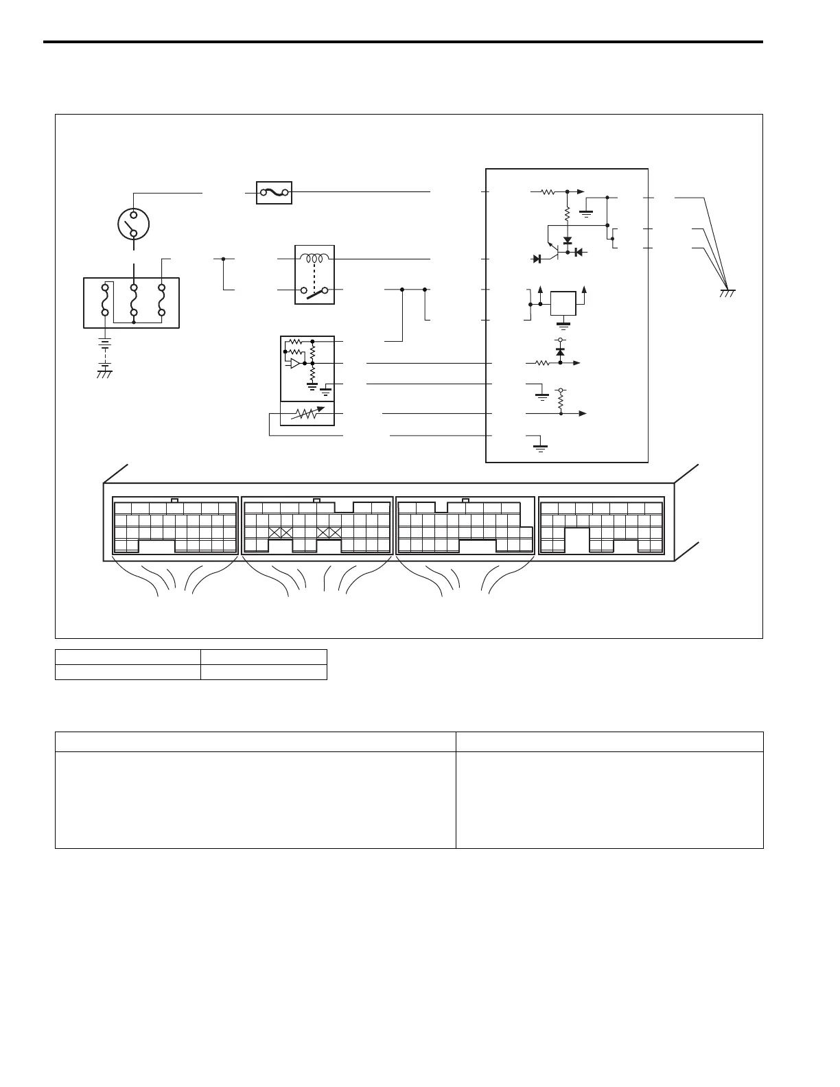
Wiring Diagram
DTC Detecting Condition and Trouble Area
DTC Confirmation Procedure
1) With ignition switch turned OFF, connect scan tool.
2) Turn ON ignition switch and clear DTC using scan tool.
3) Start engine and run it for 10 sec.
4) Check DTC and pending DTC.
1. MAF and IAT sensor 3. Main relay
2. Ignition switch 4. ECM
E23-15
E21-28
12V
5V
E21-6
E21-5
BLK/WHT
BLK/RED
BLK/RED
BLK/RED
WHT/BLU
80A
60A 20A
BLK/YEL BLK/YEL
BLK/YEL
BLU/BLK
BLU/BLK
E22-1
E23-2
BLK/YEL
BLK/YEL
BLK
E23-1
BLK/RED
WHT
E22-14
E22-32
E23 E22 E21
12345671234561234567
7
891011121314151617 8910111213141516 891011121314151617
1819
1819
1718192021222324252627 20212223 202122232425 24252627 2627
2829303132 32 282930 28293031 3133 33 323334 3435 3435
E22-17
E22-28
BRN/WHT
LT GRN
RED
2
3
1
4
DTC Detecting Condition Trouble Area
DTC will be set when all of the following conditions are
detected for 0.5 seconds continuously.
• Engine is running
• Voltage of MAF sensor output is less than the specified
value for the specified time continuously.
• Open or short in MAF sensor circuit
• MAF sensor
• ECM