ENGINE MECHANICAL (M13 ENGINE) 6A2-57
Valves and Cylinder Head Removal and
Installation
Removal
1) Remove engine assembly from vehicle referring to “Engine
Assembly Removal and Installation” in this section.
2) Remove oil pan referring to “Oil Pan and Oil Pump Strainer
Removal and Installation” in this section.
3) Remove cylinder head cover referring to “Cylinder Head
Cover Removal and Installation” in this section.
4) Remove timing chain cover referring to Steps 2) to 7) of
“Removal” in “Timing Chain Cover Removal and Installation”
in this section.
5) Remove timing chain referring to Steps 2) to 6) of “Removal”
under “Timing Chain and Chain Tensioner Removal and
Installation” in this section.
6) Remove intake and exhaust camshafts referring to Steps 3)
to 7) of “Removal” under “Camshaft, Tappet and Shim
Removal and Installation” in this section.
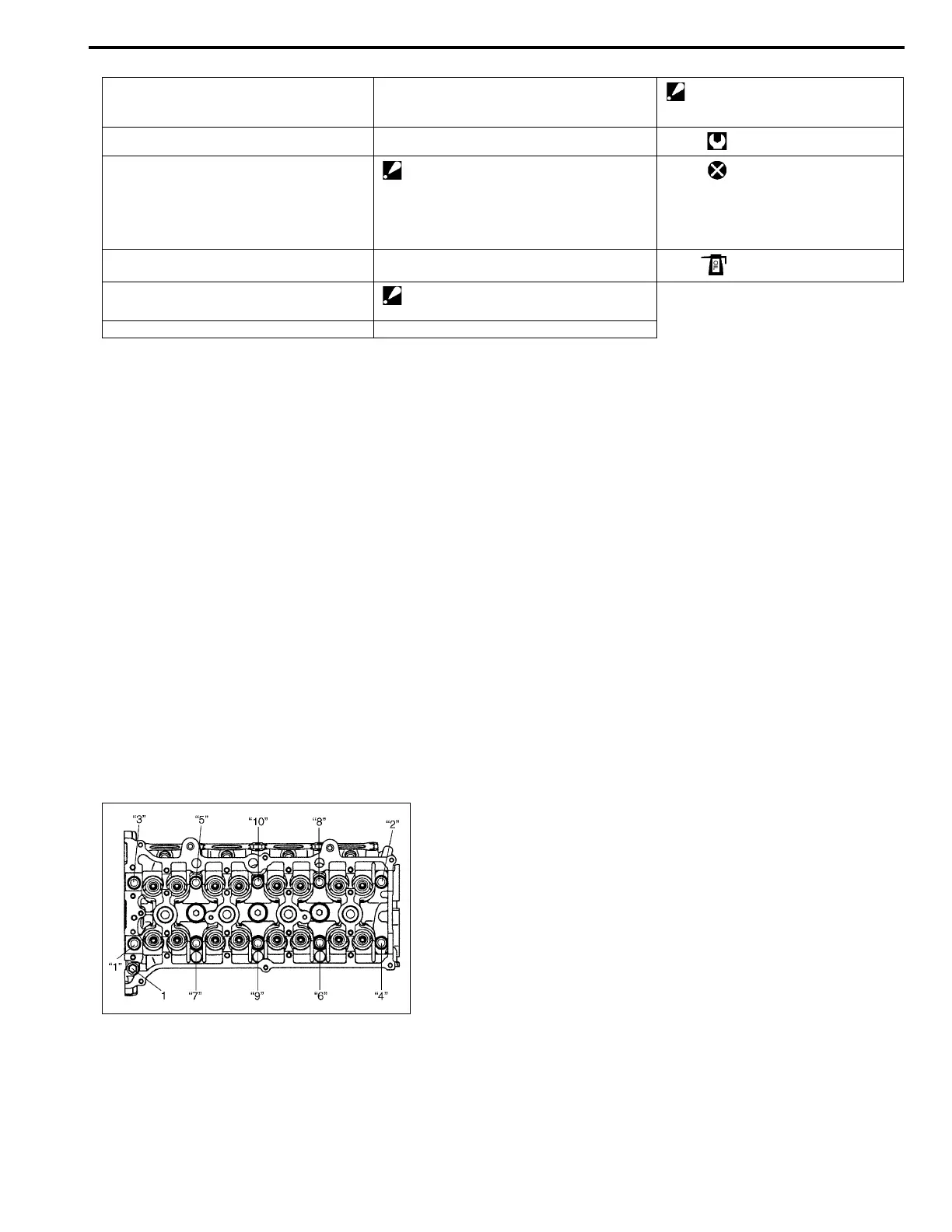
7) Loosen cylinder under head bolts in such order as indicated
in figure by using a 12 corner socket wrenches and remove
them.
8) Check all around cylinder head for any other parts required
to be removed or disconnected and remove or disconnect
whatever necessary.
9) Remove exhaust manifold, if necessary, referring to “Exhaust
Manifold Removal and Installation” in this section.
10) Remove cylinder head with intake manifold and exhaust
manifold. Use lifting device, if necessary.
1. Valve cotters 7. Exhaust valve 13. Cylinder head bolt (M8)
: Be sure to tighten cylinder head
bolt (M8) after securing the other
cylinder head bolt (M10).
2. Valve spring retainer 8. Valve guide Tightening torque
3. Valve spring 9. Cylinder head bolt (M10)
Tighten 20 N·m (2.0 kg-m, 14.5 lb-ft),
40 N·m (4.0 kg-m, 29.0 lb-ft), 60° and 60° by
the specified procedure.
: Never reuse cylinder head bolts once disas-
sembled it due to plastic deformation tighten-
ing. Be sure to use new cylinder head bolts
when installing.
Do not reuse.
4. Valve stem seal 10. Cylinder head Apply engine oil to sliding surface
of each part.
5. Valve spring seat 11. Cylinder head gasket
: “TOP” mark provided on gasket comes to
crankshaft pulley side, facing up.
6. Intake valve 12. Knock pin
NOTE:
• Don’t forget to remove bolt (M8) (1) as shown in figure.
• Never reuse cylinder head bolts once disassembled it
due to plastic deformation tightening. Be sure to use
new cylinder head bolts when installing.