6F2-2 IGNITION SYSTEM (M13 ENGINE)
General Description
Ignition System Construction
The ignition system is an electronic (distributorless) ignition system. Its consists of the parts as described below.
• ECM
It detects the engine and vehicle conditions through the signals from the sensors, determines the most suit-
able ignition timing and time for electricity to flow to the primary coil and sends a signal to the ignitor (power
unit) in the ignition coil assembly.
• Ignition coil assembly (including an igniter)
The ignition coil assembly has a built-in ignitor which turns ON and OFF the current flow to the primary coil
according to the signal from ECM. When the current flow to the primary coil is turned OFF, a high voltage is
induced in the secondary coil.
• High tension cords and spark plugs.
• CMP sensor (Camshaft position sensor) and CKP sensor (Crankshaft position sensor)
Using signals from these sensors, ECM identifies the specific cylinder whose piston is in the compression
stroke, detects the crank angle and adjusts ignition timing automatically.
• TP sensor, ECT sensor, MAP sensor, MAF sensor, IAT sensor and other sensors/switches
Refer to “Electronic Control System” in Section 6E2 for details.
Although this ignition system does not have a distributor, it has two ignition coil assemblies (one is for No.1 and
No.4 spark plugs and the other is for No.2 and No.3 spark plugs). When an ignition signal is sent from ECM to
the ignitor in the ignition coil assembly for No.1 and No.4 spark plugs, a high voltage is induced in the secondary
coil and that passes through the high-tension cords and causes No.1 and No.4 spark plugs to spark simulta-
neously. Likewise, when an ignition signal is sent to the ignitor in the other ignition coil assembly, No.2 and No.3
spark plugs spark simultaneously.
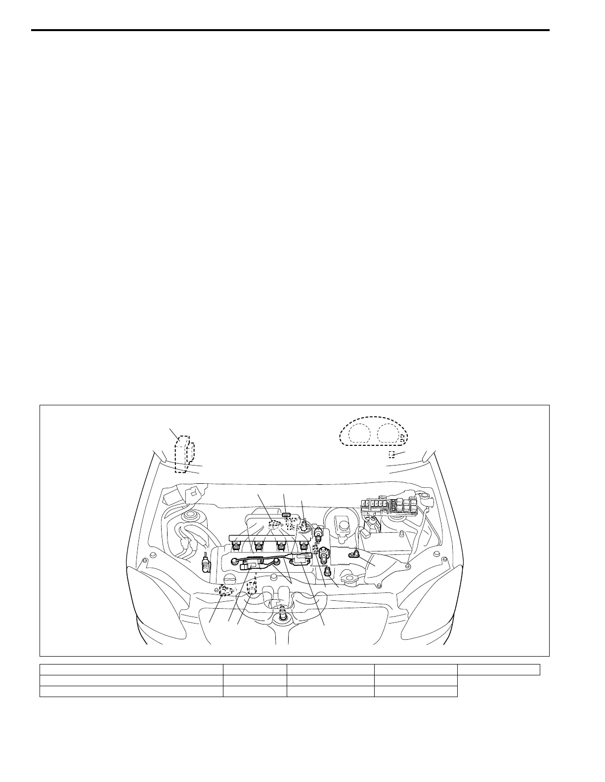
Ignition System Components Locator Diagram
1. ECM 4. CMP sensor 7. ECT sensor 10. VSS 13. Data link connector
2. Ignition coil assembly for No.1 and No.4 spark plugs 5. CKP sensor 8. MAF and IAT sensor 11. High-tension cords
3. Ignition coil assembly for No.2 and No.3 spark plugs 6. MAP sensor 9. TP sensor 12. Knock sensor
5
3
2
11
12
4
7
10
6
8
9
13*
1*
NOTE:
Above figure shows left-hand steering vehicle. For right-hand steering vehicle, parts with (*) are
installed at the opposite side.