MANUAL TRANSAXLE (M13 ENGINE) 7A2-19
Gear Shift and Select Shaft Disassembly and
Assembly
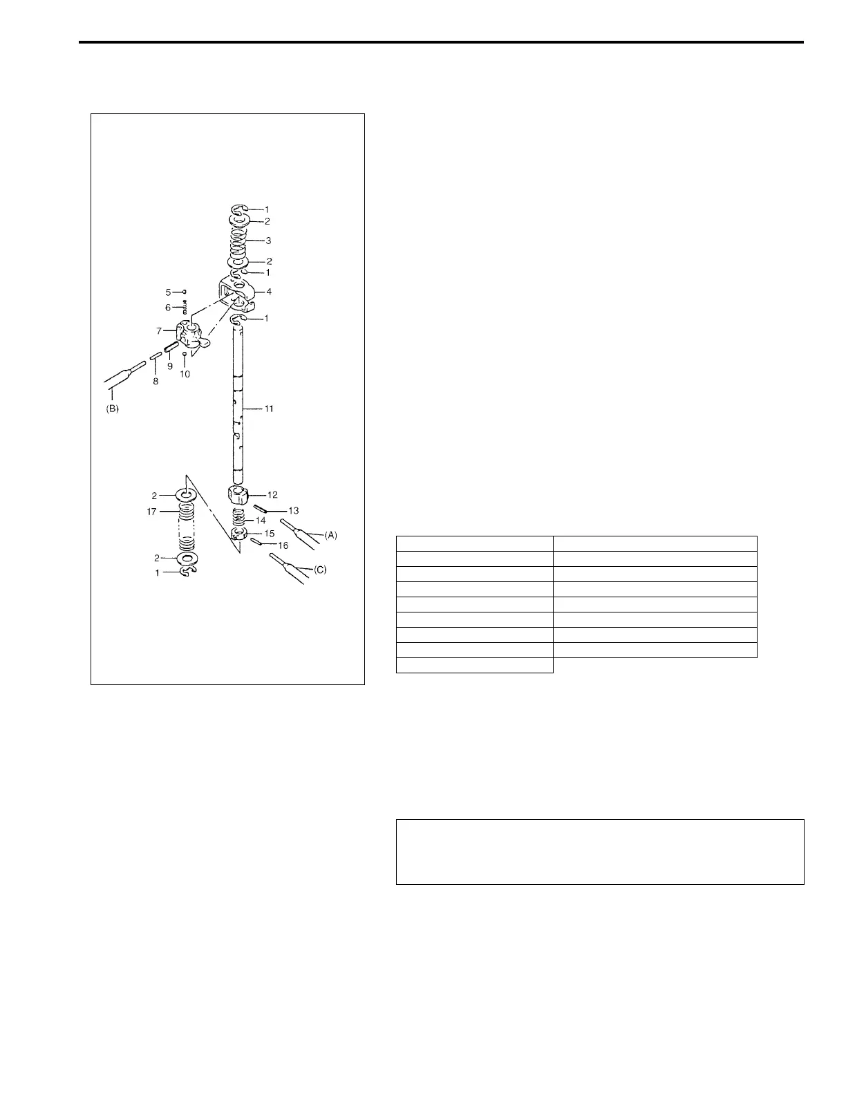
1) Push spring pins out using specified spring pin removers as
shown bellow.
Special tool
(A): 09922-85811 (4.5 mm)
(B): 09925-78210 (6.0 mm)
(C): 2.8 – 3.0 mm (0.11 – 0.12 in.) Commercially available
spring pin remover
2) Inspect component parts for wear, distortion or damage. If
any detect is found, replace detective part with new one.
Fifth Gear Disassembly and Assembly
Disassembly
1) Remove side cover bolts and take off transaxle side cover.
NOTE:
• When driving in spring pins, prevent shaft from being
bent by supporting it with wood block.
• Assemble 5th & reverse gear shift cam with its pit and
spring pin aligned.
• Make sure to select an appropriate spring by identify-
ing the painted colors to keep gear shifting perfor-
mance as designed.
– Low speed select spring - No paint
– Reverse select spring - Pink
1. E-ring 10. Ball
2. Washer 11. Gear shift & select shaft
3. Reverse select spring 12. 5th & reverse gear shift cam
4. Gear shift interlock plate 13. Spring pin
5. Ball 14. Cam guide return spring
6. Gear shift interlock spring 15. 5th & reverse gear shift cam guide
7. Gear shift & select lever 16. Spring pin
8. Spring pin 17. Low speed select spring
9. Spring pin
CAUTION:
Care should be taken not to distort side cover when it is
removed from left case.