7A2-26 MANUAL TRANSAXLE (M13 ENGINE)
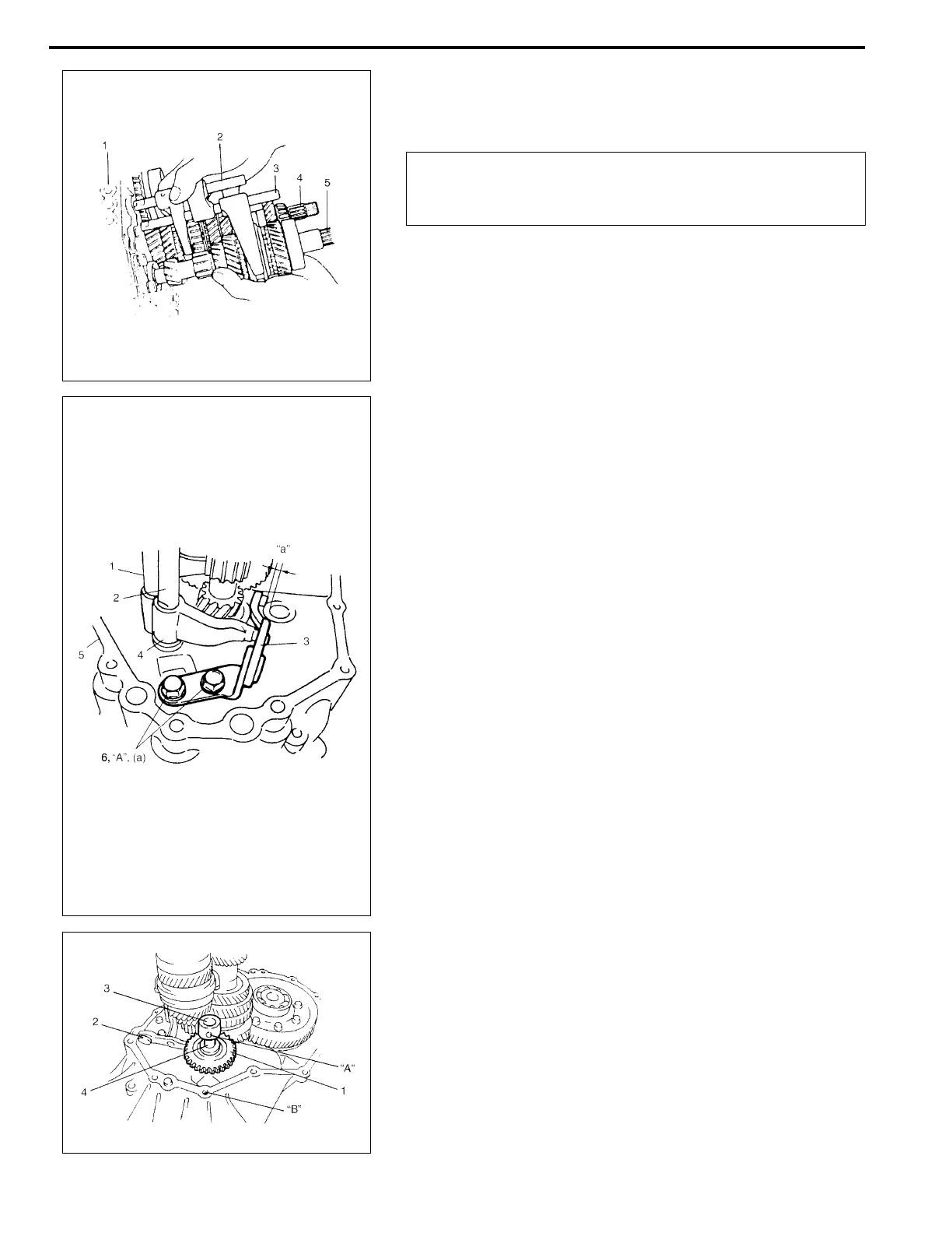
3) Join input shaft (5), countershaft (4), low speed gear shift
shaft (2) and high speed gear shift shaft (3) assemblies all
together, then install them into right case (1).
4) Install 5th & reverse gear shift shaft (1) with 5th & reverse
gear shift guide shaft (2) into right case (5). Reverse gear
shift arm (4) has to be joined with reverse gear shift lever (3)
at the same time.
5) Place reverse gear shift lever (3), fasten it with bolts (6) after
applying thread lock cement.
“A”: Thread lock cement 99000-32110
Tightening torque
Reverse gear shift lever bolt
(a): 23 N·m (2.3 kg-m, 17.0 lb-ft)
Distance between lever end and shaft bore
“a”: 5 mm (0.2 in.)
6) Make reverse idler gear (1) with reverse gear shift lever (2),
insert reverse gear shaft (3) into case through idler gear and
then align “A” in shaft with “B” in case.
CAUTION:
Take care not to damage oil seal lip by input shaft, or oil
leakage may take place.
NOTE:
• Input shaft right bearing on shaft can be installed into
right case tapping shaft with plastic hammer.
• Check to make sure that counter shaft is engaged with
final gear while installing.
NOTE:
• When installing reverse gear shift lever (3), set it as the
following specification.
• Distance “a” must be measured after installing reverse
gear shaft.
• When “a” is 5 mm (0.2 in.), clearance between reverse
idler gear groove and shift lever end will be 1 mm (0.04
in.).
NOTE:
• Make sure that washer (4) has been installed in shaft at
above the gear.
• Check to confirm that reverse gear shift lever end has
clearance 1 mm (0.04 in.) to idler gear groove.