AUTOMATIC TRANSAXLE (M13 ENGINE) 7B1-153
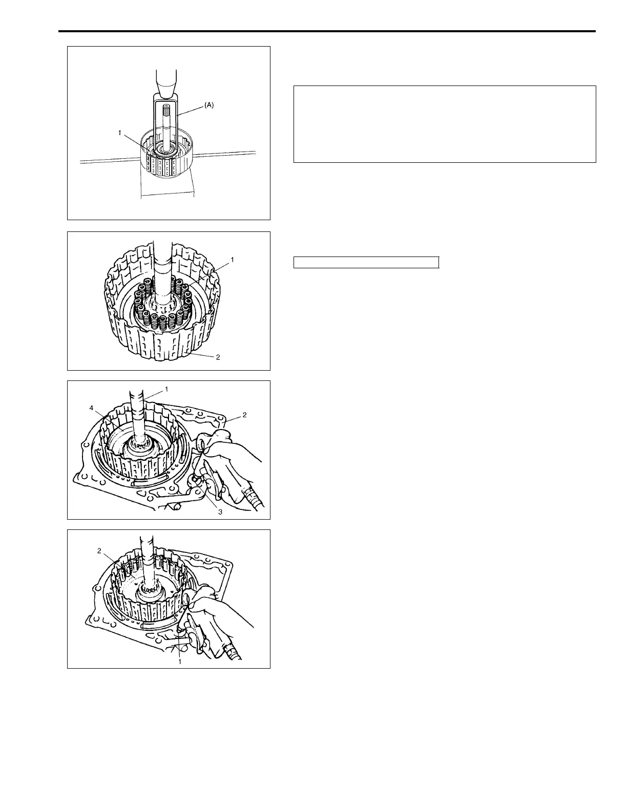
3) Remove balancer snap ring by using special tool and
hydraulic press.
Special tool
(A): 09926-97610
4) Remove forward clutch balancer (1).
5) Remove forward clutch return spring subassembly (1).
6) Install intermediate shaft subassembly (1) to transaxle rear
cover (2). Apply compressed air (400 – 800 kPa, 4 – 8 kg/
cm
2
, 57 – 113 psi) to oil hole (3) of transaxle rear cover to
remove forward clutch piston (4).
7) Apply compressed air (400 – 800 kPa, 4 – 8 kg/cm
2
, 57 –
113 psi) to oil hole (1) of transaxle rear cover to remove for-
ward clutch drum (2).
CAUTION:
Do not press forward clutch return spring subassembly
in over 1.5 mm (0.059 in.).
Excessive compression may cause damage to return
spring subassembly and/or balancer.
2. Intermediate shaft subassembly