8G-2 IMMOBILIZER CONTROL SYSTEM (G10/M13 ENGINES)
General Description
Components
The immobilizer control system designed to prevent vehicle burglar and it consists of following components.
• Engine control module (ECM)
• Immobilizer control module (with coil antenna)
• Ignition key (with built-in transponder)
Operations
1) Each ignition key has its own FIX CODE (FC) stored in memory. When the ignition switch is turned to ON (II)
position, immobilizer control module reads the FC through its coil antenna from ignition key.
2) Immobilizer control module compares FC read in step 1 and that registered in immobilizer control module
and checks if they match.
3) ECM sends variable (generated randomly) to transponder via immobilizer control module, and then ECM
calculates it with SECRET KEY (SKC) stored in its memory according to specified algorithm. On the other
hand, transponder also calculates received variable with SKC stored in memory by means of same algo-
rithm and sends back to ECM.
4) Only when ECM/transponder calculated values match, ECM keeps running engine. If two calculated values
do not match, ECM stops operation of injectors and ignitor to stop engine after about 1.8 seconds at the first
time. After the second time, ECM does not let engine start. And, so it does when FIX CODEs in step 2 do not
match.
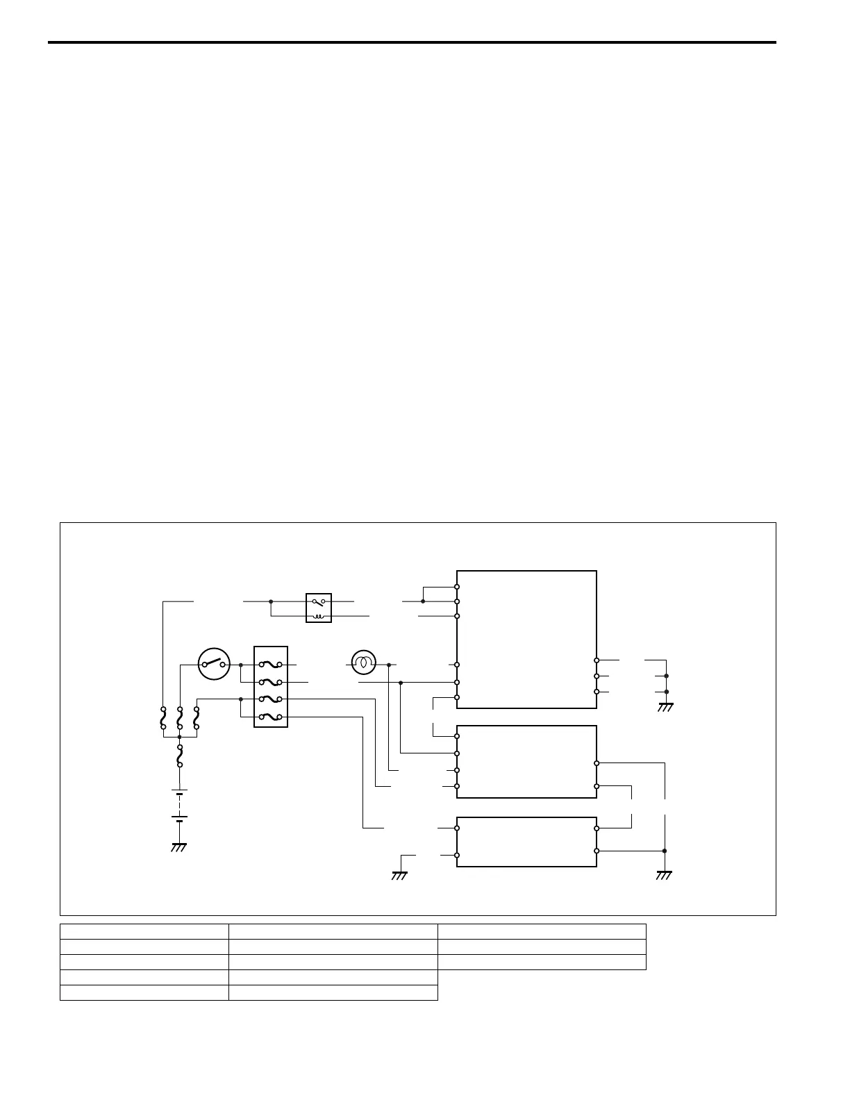
Wiring Circuit for M13 Engine Model
1. Battery 6. DOME RADIO fuse (15 A) 11. Data link connector (DLC)
2. Fuse 7. STOP fuse (15 A) 12. Immobilizer Control Module
3. FI fuse (20 A) 8. IG COIL fuse (15 A) 13. ECM
4. Ignition switch 9. METER fuse (10 A)
5. Main relay 10. Immobilizer indicator lamp
4
9
13
22
2
E21-2
E23-1
E23-2
E22-1
E21-28
E21-11
BLK/YEL
BLK
BLK/YEL
12
G17-7
G17-5
G17-2
G17-9
G17-4
G17-6
G09-7
11
G09-16
G09-4
G09-5
1
8
7
6
BLK/RED
WHT/BLK
BLK/WHT
10
PPL/WHT
PPL/WHT
GRN/RED
WHT/BLU
BLK
BRN
BLK
3
E21-5
E21-6
E23-15
BLK/RED
BLU/BLK
BLK/YEL
5