SVAN 979 User Manual - Appendixes
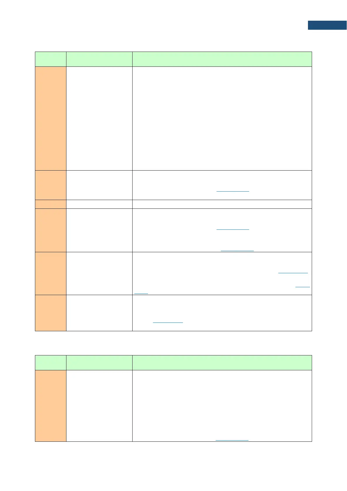
Table B.2.1. Block of primary results record (data name in square brackets means data is optional)
bit 0 (overload flag):
0 – no overload
1 – overload occurred
bit 1 (excessive vibration flag):
0 – no excessive vibration
1 – excessive vibration
bits 2..7 – reserved
bits 8..(7+n) – underrange flags in “n” profiles:
0 – the signal level is equal to or greater than the declared lower
range of measured values
1 – the signal level is lower than the declared lower range of
measured values
remaining bits are reserved
measurement results of the first profile:
– number and order of results is determined by the result bit mask in
the profile parameter block (see Table B.1.14, the word "LoggerRes")
– results are in format 0,01 dB
measurement results of the n
th
profile:
– number and order of results is determined by the result bit mask in
the profile parameter block (see Table B.1.13, the word "LoggerRes")
– results are in format 0,01 dB,
– The number of profiles comes from the corresponding parameter
in the main parameter block (see Table B.1.12, the word "00nxxh").
lowest and highest word of the RPM measurement result value:
– result is available if the RPM measurement is enabled (see the
word "RPM_On" in the measurement parameter block - Table B.1.7)
– value of the result is calculated according to the formulas given in
the comment of the RPM measurement results block (see Table
B.3.5)
results of the spectrum measurement:
– results are available if the spectra recording during measurement
is enabled (see the word "SpecLogg" in the measurement parameter
block - Table B.1.7)
– results are in format 0,01 dB
Table B.2.2. Block of user marker (only one word)
08h = block identifier
0nnnh = bit mask of markers states:
– each bit specifies the state of one marker (the lowest bit
defines the state of the first marker, the next bit defines the
state of the next marker, and so on.)
– set bit indicates that the marker is active
– erased bit indicates that the marker is inactive
– number of available markers (maximum 12) and marker
type (block or spot) are defined in the corresponding
parameter block (see Table B.1.16)