15
Integrated Fiber Optic Module
266 Evolution 200 Series User Guide Thermo Scientific
8. Turn on the spectrophotometer and wait until it initializes. See Using the
Spectrophotometer.
9. If the instrument has the Application Focused Beam Geometry™ (AFBG) option, select
an application, click Settings > Instrument and set Bandwidth to Fiber.
10. Align the accessory.
Related Topics
Attaching Cables and Probes
Aligning the Accessory
Attaching Cables and Probes
The accessory is compatible with probes and cables that have SMA connectors. Contact us for
compatible probes. See Contacting Us.
Install the accessory and align it before installing cables and probes.
Y To attach cables and probes
1. Remove the protective caps from the probe cables and accessory ports.
Store the caps securely so they can be replaced when the probe or accessory is removed
from the instrument.
2. Route the cables through the detector compartment on the instrument.
3. Attach the probe’s Light Input cable to the Light Output port on the accessory.
To attach a cable, insert the SMA connector and gently tighten the ferrule by hand.
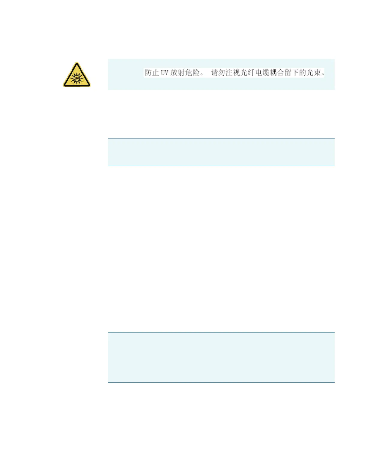
WARNING
Note If you change the application, reset Bandwidth to Fiber, or create a template
for fiber optic sampling for this application and save your data in a workbook based
on that template.
NOTICE When attaching fiber optic cables to the accessory ports, avoid:
• Twisting or bending the cable.
• Touching the tips with your fingers.
• Overtightening or using tools to tighten the connectors.