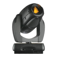
MAINTENANCE PROCEDURES : MAIN CONTROL BOARD (MCB) PCB REPLACEMENT
02.9678.0010 F 27
2
Main Control Board (MCB) PCB Replacement
VL Part No: 24.9678.3730
Repair/Replacement Procedure
Step 1. Disconnect luminaire AC input cable from power source.
Note: To determine which yoke leg is which without having to remove the covers, rotate yoke
counterclockwise until it stops, then look at the luminaire while facing the input panel. The tilt-side leg
is the leg to the left; the board-side leg is the leg to the right.
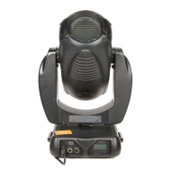
Step 2. At board-side leg, remove yoke leg cover by removing four 6-32x5/16" PPB screws.
CAUTION: Always use anti-static precautions when working with PCBs.
Step 3. Disconnect wiring harness connectors J8, J9, J10 and J11.
Step 4. Remove four (4) 6-32 screws securing MCB PCB
Step 5. Disconnect upper enclosure connectors J1, J2, J3, J4 and J12 at back of MCB.
Step 6. Install replacement assembly by performing Steps 2-5 in reverse order.
Step 7. Configure using menu functions as necessary.
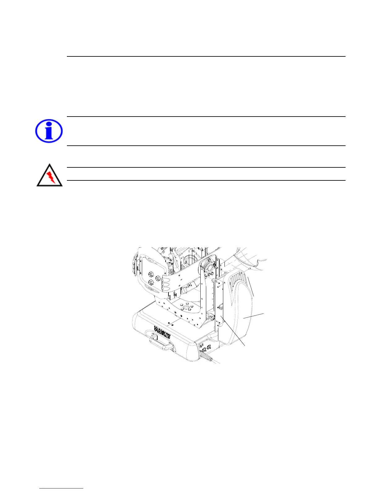
Figure 2-9: VL3000 Main Control Board Replacement
Main Controller Board
Yoke Leg Cover