VARI❋LITE® - VL3000™ SERIES LUMINAIRE SERVICE MANUAL
44 02.9678.0010 F
Tilt Encoder PCB Replacement
VL Part No: 24.9661.9629
Repair/Replacement Procedure
Step 1. Disconnect luminaire AC input cable from power source.
Step 2. At tilt-side leg, remove yoke leg cover by removing four 6-32x5/16" PPB screws.
Step 3. At tilt motor assembly, loosen four 10-32x1/2" PPZ screws.
Step 4. Remove belt from tilt pulley.
Step 5. Remove four 10-32x1/2" PPZ screws. Be mindful of tensioning springs.
Step 6. Disconnect wiring and remove tilt assembly.
Step 7. On tilt assembly, remove two 4-40x1/4" LG PPZ screws and remove encoder PCB.
Step 8. Replace by performing steps 2 through 7 in reverse order.
Note: Make sure encoder disk passes through sensor when installing encoder PCB and wiring is not
pinched during installation. When tightening four 10-32x1/2" PPZ screws that mount Pan Motor
Assembly, you must tighten in a CLOCKWISE pattern starting with screw in lower left-hand side
from spring.
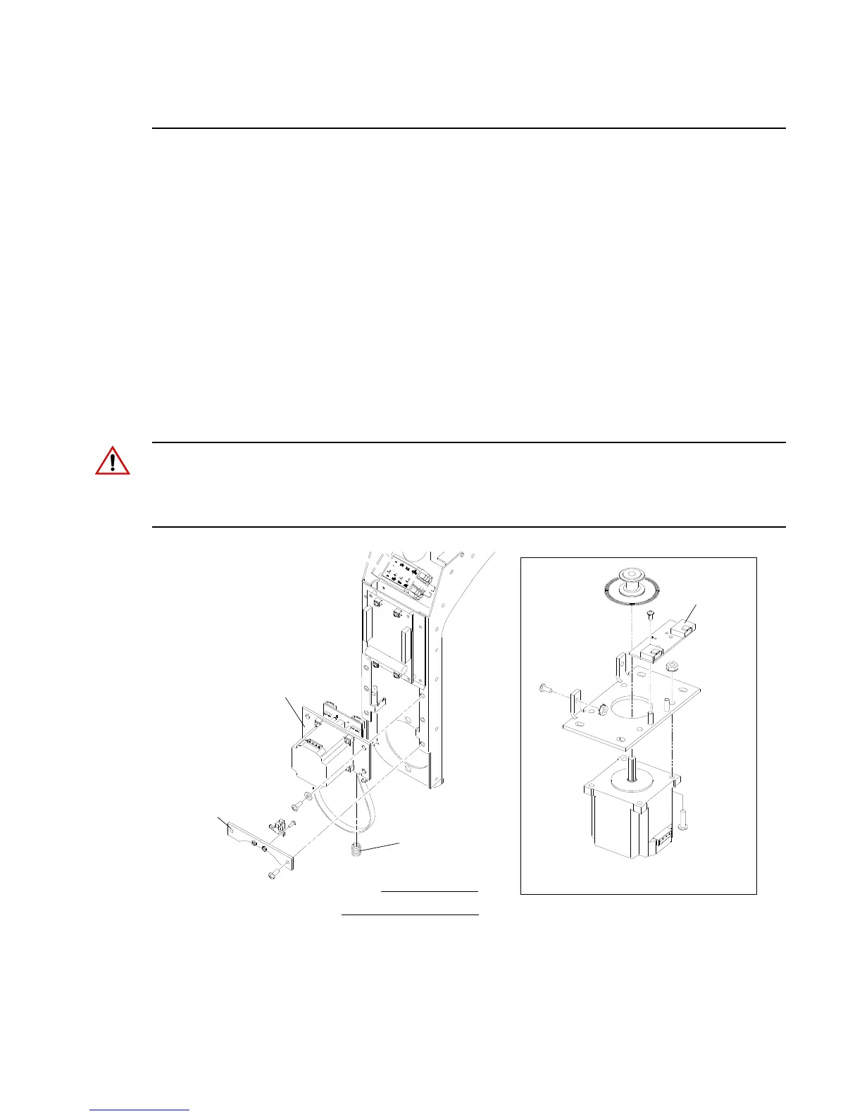
Figure 2-24: VL3000 Tilt Encoder PCB Replacement
Tilt Motor
Assembly
Spring
Head not shown for clarity.
NOTE:
Tilt Encoder
Tilt Motor Assembly Detail
Sensor
Bracket
1)
2)