MAINTENANCE PROCEDURES : GOBO ASSEMBLY REPLACEMENT
02.9678.0010 F 35
2
Gobo Assembly Replacement
VL Part No: 21.9678.0200
Repair/Replacement Procedure
Step 1. Run Edge to full forward position (DMX 255).
Step 2. Disconnect luminaire AC input cable from power source.
Step 3. Remove top head cover by loosening four quarter-turn captive locking screws. Top cover is
identifiable as the cover on top when back label is such that words are displayed correct side
up.
Step 4. Disconnect head cable from Color Assembly Interconnect PCB, remove wiring from
Transfer Fan clips.
Step 5. Disconnect Transfer Fan wiring from Zoom Interconnect PCB.
Step 6. Disconnect head cable from Gobo Assembly Interconnect PCB.
Step 7. At Gobo Assembly clamps, loosen four 6-32 captive screws (two per clamp) and remove
clamp. (Note: the large Phillips screw in the middle is used as a handle, DO NOT try to
loosen that screw).
Step 8. Pull Gobo Assembly straight out of fixture.
Step 9. Replace by performing steps 3 through 8 in reverse order.
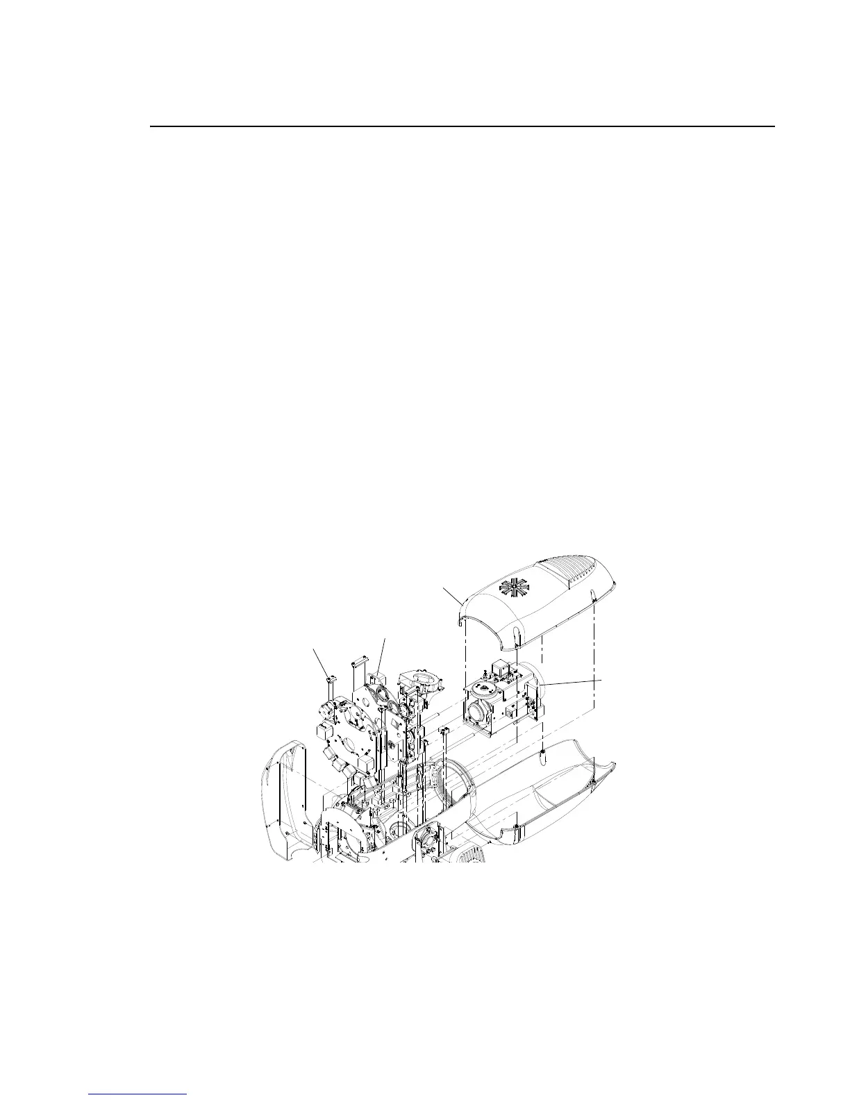
Figure 2-16: VL3000 Spot Gobo Assembly Replacement
Gobo Assembly
Optic Assembly
(Must be all the way forward.)
Top Head Cover
Clamp