MAINTENANCE PROCEDURES : DISPLAY PCB ASSEMBLY REPLACEMENT
02.9678.0010 F 55
2
Display PCB Assembly Replacement
VL Part No: 24.9678.3825
Repair/Replacement Procedure
Step 1. Disconnect luminaire AC input cable from power source.
Step 2. At enclosure, remove two 6-32x1/4" LG PPZ screws from display side cover and remove
cover.
Step 3. At power supply, disconnect wiring:
Step 4. Remove one 6-32x3/8" LG PPZ screw.
Step 5. Loosen two 6-32x3/8" LG PPZ screws and slide LVS towards upper enclosure fan to
remove.
Step 6. At Display PCB, remove two 6-32x3/8" PPZ screws, remove Display stiffener bracket and
lift PCB out of slot on bottom of chassis.
Step 7. Carefully disconnect wiring from PCB.
Step 8. Replace by performing steps 2 through 7 in reverse order.
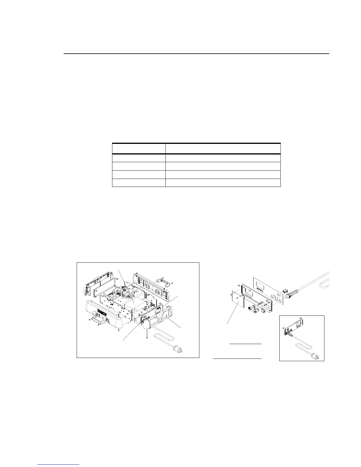
Figure 2-21: VL3000 Display PCB Assembly Replacement
Location Connector
N White AC Wires
L Black AC Wires
V + Red DC Wires
V - Black DC Wires
Some components not
NOTE:
Display Cover
Display
Display PCB
Display Panel Assembly
Display Panel Assembly
LVS Power Supply
shown for clarity.