MAINTENANCE PROCEDURES : SPOT OPTIC ASSEMBLY REPLACEMENT
02.9678.0010 F 41
2
Step 19. Finish by performing steps 2 through 4 in the removal section in reverse order.
Note: To prevent binding, thread edge screw all the way into linear actuator motor before re-
installing. Secure right-side optic assembly clamps first when re-installing.
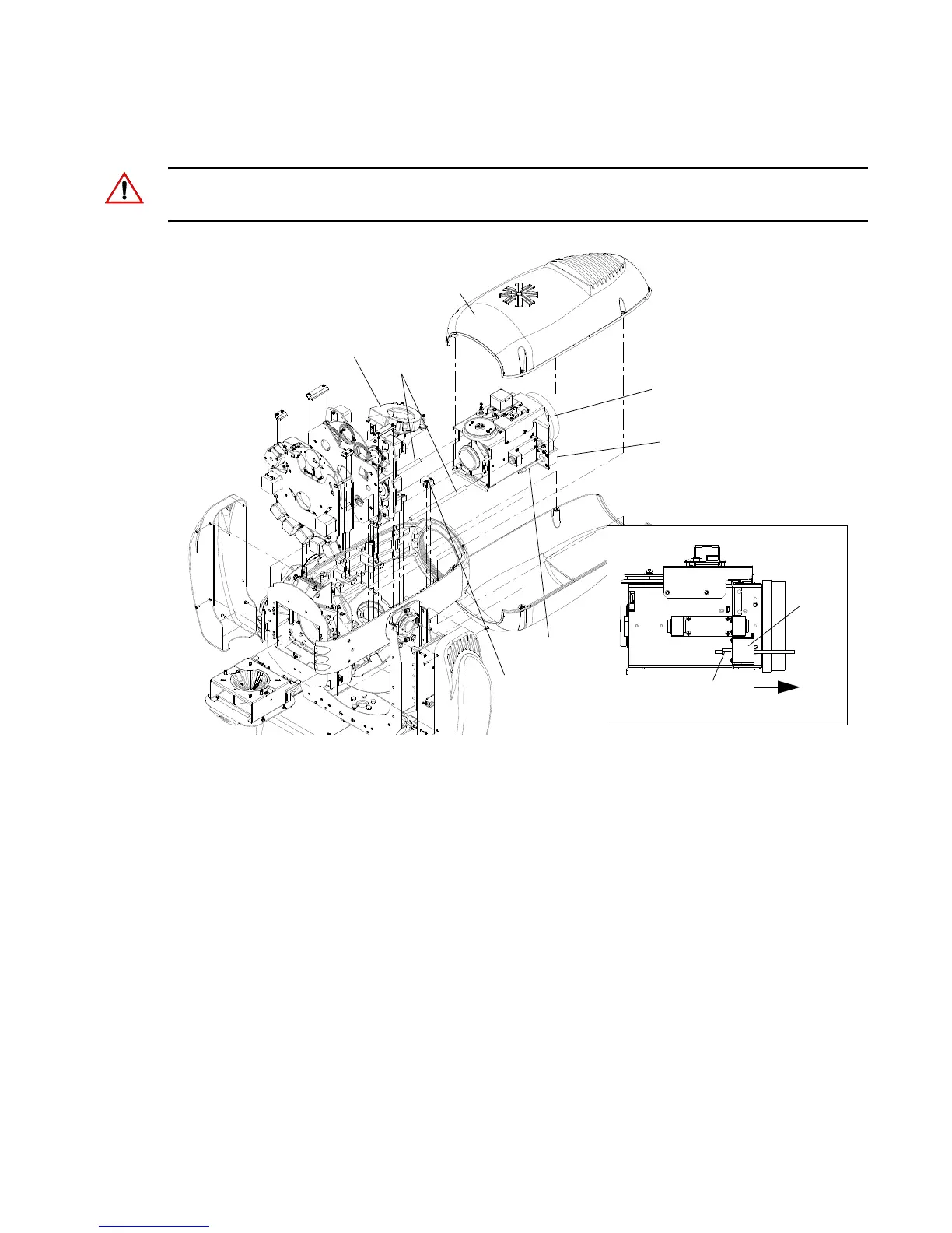
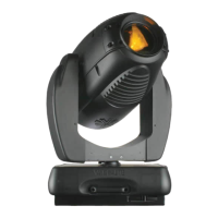
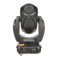
Figure 2-22: VL3000 Spot Optic Assembly Replacement
Spot Optic Assembly
Top Head Cover
Fan
Guide Rod
Linear Actuator
Motor (see detail)
Thread all the way into motor
as shown before re-installing.
Optic Assembly Side View
Edge
Screw
Edge Screw
Motor
Clamp
(Secure this side
first when re-
installing.)