09/2007
4-23
Phaser 8860/8860MFP Service Manual
REP 2.0.3
Repairs and Adjustments
Initial Issue
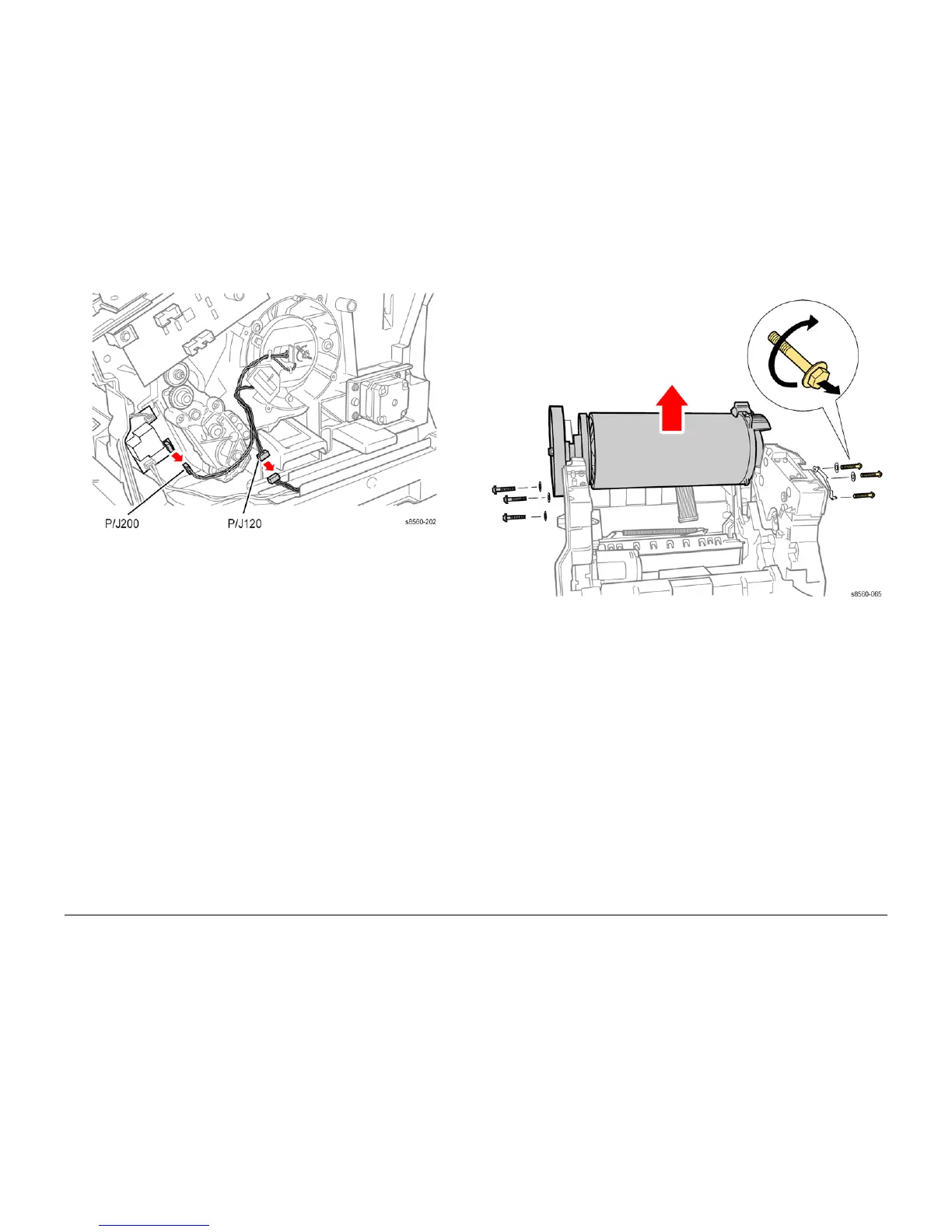
Figure 2 Disconnecting the Drum
16. Disconnect the Drum Encoder harness P/J120 from the Right Side Harness and release
the cable from the restraint.
17. Remove 3 (metal, 5.5 mm hex-head) screws, 2 washers, and the Ground Plate from the
right side of the Drum Assembly as shown in Figure 3. These are reverse-threaded
screws as indicated on the label attached to the Drum.
Figure 3 Removing the Drum Assembly
18. Remove 3 (metal, T-20) screws and 3 washers from the left side of the Drum Assembly.
NOTE: Do not rest the Drum Assembly on the pulley. Allow the pulley to overhang the sur-
face and rest the assembly on its feet.
19. Lift the Drum Assembly straight out of the chassis using the metal grips provided.
Replacement
CAUTION
The Drum Temperature Sensor harness is routed through the Exit Module. Use care when
reinstalling to avoid damaging the sensor.
NOTE: To help seat the Drum properly, steps 2-6 provide an explicit order of placement for
installing the screws to secure the Drum Assembly to the chassis.
1. Seat the Drum Assembly into the chassis.
2. Align the screw holes in the left and right sides of the Drum Assembly to the holes in the
chassis sides.
3. Install 1 (metal, T-20) screw and washer at the rear position on the left side to hold the
Drum Assembly and torque the screw to 25 in.-lbs.
4. Install the remaining (metal, T-20) screws and washers into the left side of the Drum
Assembly and torque to 25 in.-lbs.