09/2007
4-55
Phaser 8860/8860MFP Service Manual
REP 4.0.10, REP 4.0.11
Repairs and Adjustments
Initial Issue
REP 4.0.10 Tray 2 Lift Motor Gear
Parts List on PL 4.0
Removal
1. Remove the Electronics Module (REP 5.0.5).
2. Remove Tray 2.
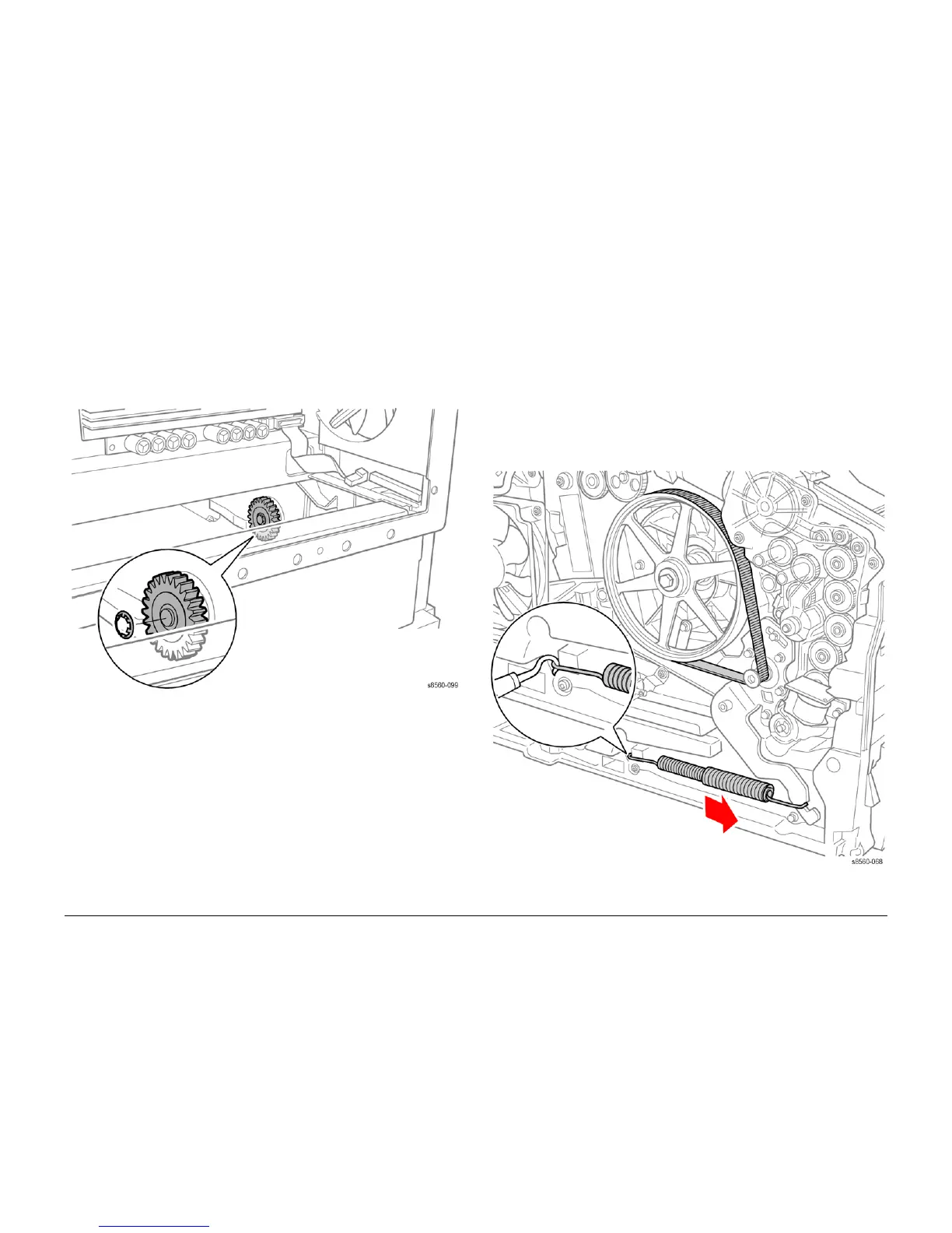
3. Remove the Lift Motor Gear by prying the Push Nut off the shaft. Replace the Push Nut
with a new one when installing the gear.
Figure 1 Removing the Lift Motor Gear
Replacement
Check that the bushing tabs are properly seated in the chassis. To seat the new Push Nut,
position the Push Nut so the fingers point away from the shaft. Place a 3/8 in. nut driver over
the nut and press firmly to seat the nut on the shaft.
REP 4.0.11 Y-Axis Motor Assembly
Parts List on PL 4.0
Removal
NOTE: These steps describe Y-Axis Motor removal for the 8860MFP. On 8860 models, access
the Y-Axis Motor by removing the Control Panel Cover (REP 1.1.5). Afterwards, return to this
procedure and begin at Step 3.
1. Remove the Scanner Assembly with attached DADF (REP 1.0.11).
2. Remove the Output Tray (REP 1.0.6).
3. Remove the Left Side Cover (REP 1.0.7 or REP 1.1.9 for the 8860).
4. Release tension on the Y-Axis Belt by pulling the end of the Spring Arm toward the front of
the printer.
Figure 1 Removing the Y-Axis Spring

 Loading...


