09/2007
4-31
Phaser 8860/8860MFP Service Manual
REP 2.0.8, REP 2.0.10
Repairs and Adjustments
Initial Issue
Replacement
CAUTION
Torque the Printhead Restraint screws to 6 in. lbs. Irreversible damage can result from over-
tightening these fasteners.
Check that the Left Printhead Restraint does not interfere with the Roll Block. Also, make sure
the Tilt Spring on the Left Printhead Restraint is properly positioned in the notch on the back of
the Printhead and does not pinch the Air Hose.
Perform the Head Tilt Gear (ADJ 4.13.1), and Process Drive Alignment (ADJ 4.7.1) adjust-
ments before restoring system power.
REP 2.0.10 Transfix Camshaft
Parts List on PL 2.0
Removal
CAUTION
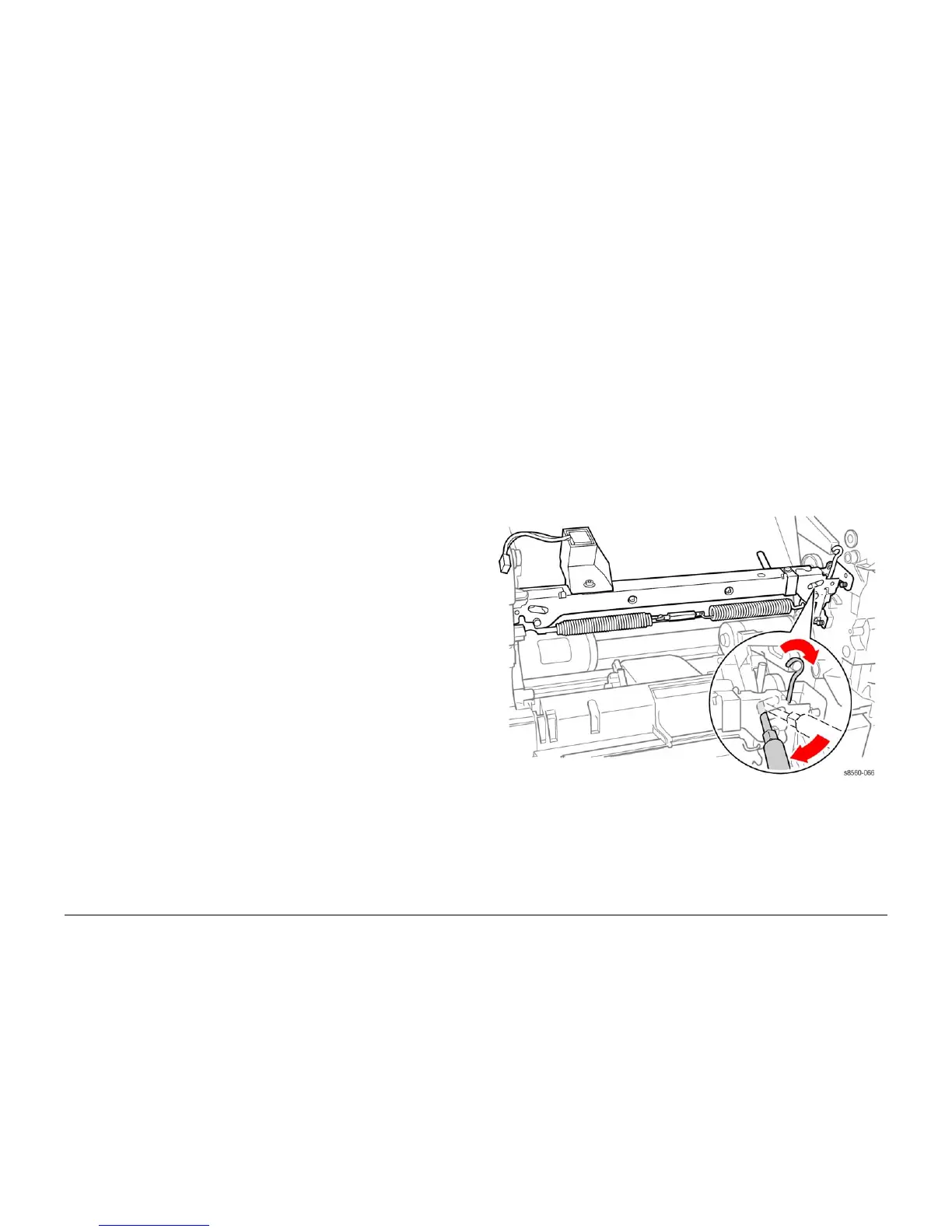
Use care when releasing the Transfix Module spring hooks. Move your lever handle towards
the center of the system as indicated in Figure 1.
1. Remove the Ink Loader (REP 2.0.1 or REP 1.1.8 for the 8860).
2. Remove the Media Drive Assembly (REP 4.0.14).
3. Remove the Exit Module (REP 3.0.7 or REP 3.1.13 for the 8860).
4. Remove the Duplex Roller (REP 3.0.4).
5. Remove the Upper Duplex Guide and Solenoid (REP 3.0.5).
6. Insert a T-20 Torx bit through the right side slotted hole in the Transfix Load Module.
Engage the hole at the back of the module, and lever the module’s spring cam towards
the center of the printer while disconnecting the spring hooks from the Transfix Load
Arms. Repeat this process for the left side.
Figure 1 Detaching the Transfix Load Module Spring Hooks
7. Remove the Process Drive Gearbox (REP 4.0.7).
8. Slide the camshaft to the right, making sure the bearing slides over to the gear. Move the
camshaft down and slightly to the right, and then up to the left to remove it from the chas-
sis.