09/2007
4-54
Phaser 8860/8860MFP Service Manual
REP 4.0.8, REP 4.0.9
Initial Issue
Repairs and Adjustments
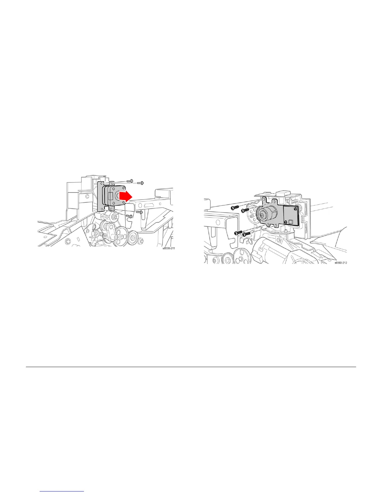
REP 4.0.8 Exit Roller Motor (8860MFP)
Parts List on PL 4.0
Removal
1. Remove the Scanner Assembly with attached DADF (REP 1.0.11).
2. Remove the Output Tray (REP 1.0.6).
3. Remove the Right Side Cover (REP 1.0.21).
4. Disconnect the motor (P/J309) from the harness.
5. Remove 4 (plastic, T-20) screws, one with a ground strap that secure the motor to the
chassis.
Figure 1 Removing the Exit Roller Motor
6. Remove the KL-Clip that secured the pulley on the motor shaft and transfer the pulley to
the replacement motor.
Replacement
CAUTION
When replacing the Exit Roller Motor screws, torque to no more than 12 in.-lbs. Overtightening
these fasteners can result in irreversible damage to the chassis.
REP 4.0.9 Exit Elevator Motor (8860MFP)
Parts List on PL 4.0
Removal
1. Remove the Scanner Assembly with attached DADF (REP 1.0.11).
2. Remove the Output Tray (REP 1.0.6).
3. Remove the Left Side Cover (REP 1.0.7).
4. Disconnect the Speaker.
5. Mark the position of the leads and disconnect the Exit Elevator Motor (P/J303) from the
harness.
6. Remove 4 (plastic, T-20) screws, that secure the motor to the chassis.
NOTE: Transfer the Speaker to the replacement motor bracket.
Figure 1 Removing the Exit Elevator Motor
Replacement
CAUTION
When replacing the Elevator Motor screws, torque to no more than 12 in.-lbs. Overtightening
these fasteners can result in irreversible damage to the chassis.
If the Elevator Motor leads (P/J320) are reversed during replacement, on power-up, the system
enters a fault state without displaying a fault code. This state is indicated by the LED on the Exit
Module Control Board flashing and media jams in the Exit Module.