09/2007
4-64
Phaser 8860/8860MFP Service Manual
REP 5.0.1, REP 5.0.2
Initial Issue
Repairs and Adjustments
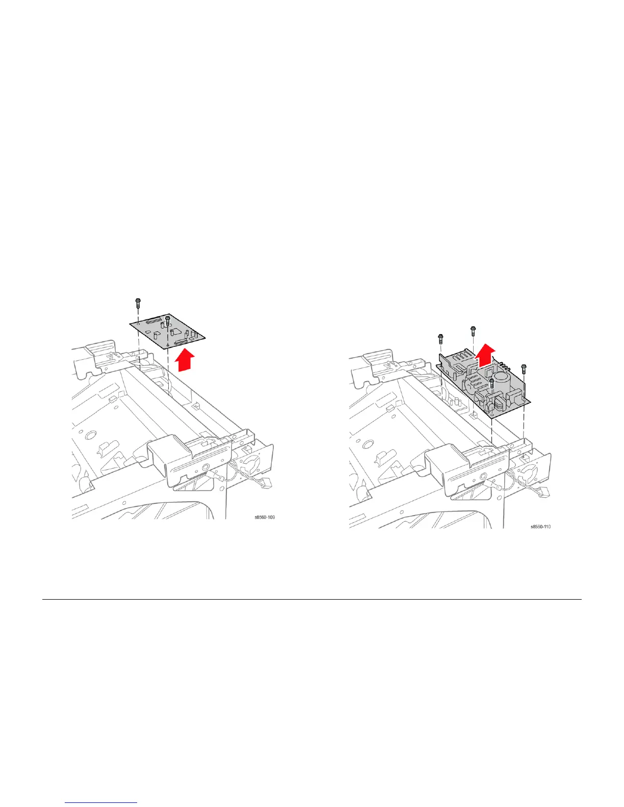
REP 5.0.1 Exit Module Control Board (8860MFP)
Parts List on PL 5.0
Removal
1. Remove the Scanner Assembly with attached DADF (REP 1.0.11).
2. Remove the Output Tray (REP 1.0.6).
3. Remove the Left Side Cover (REP 1.0.7).
4. Remove the Right Side Cover (REP 1.0.21).
5. Remove the Rear Cover (REP 1.0.20).
6. Disconnect all connections to the Exit Module Board.
7. Remove 2 (metal, T-20) screws that secure the board to the Back Frame.
Figure 1 Removing the Exit Module Control Board
REP 5.0.2 Scanner Power Supply (8860MFP)
Parts List on PL 5.0
Removal
WARNING
Disconnect the AC Power Cord before servicing the system. The Scanner Power Supply
connects directly to the AC Line.
1. Remove the Scanner Assembly with attached DADF (REP 1.0.11).
2. Remove the Output Tray (REP 1.0.6).
3. Remove the Left Side Cover (REP 1.0.7).
4. Remove the Right Side Cover (REP 1.0.21).
5. Remove the Rear Cover (REP 1.0.20).
6. Disconnect all connections to the Scanner Power Supply.
7. Remove 4 (metal, T-20) screws that secure the Scanner Power Supply to the Back Frame.
Figure 1 Removing the Scanner Power Supply