09/2007
4-73
Phaser 8860/8860MFP Service Manual
REP 6.0.6, REP 6.0.7
Repairs and Adjustments
Initial Issue
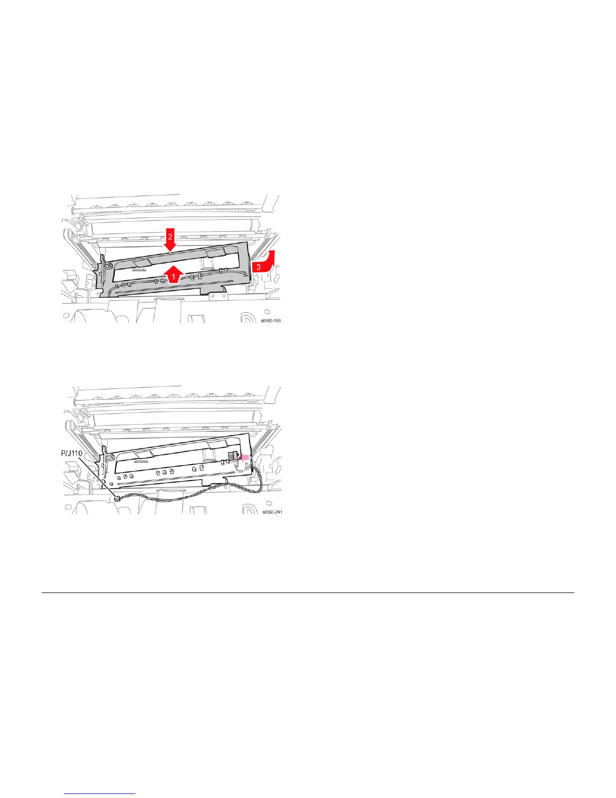
Figure 2 Removing the Waste Tray Cover
8. Disconnect the Waste Tray Detect Sensor (P/J110) from the I/O Board.
9. Unlace the sensor harness from the retainers and guides.
10. Release the hooks that secure the sensor to the cover and remove the sensor.
Figure 3 Removing the Waste Tray Detect Sensor.
Replacement
Perform the Head Tilt Gear (ADJ 4.13.1), and Process Drive Alignment (ADJ 4.7.1) adjust-
ments before restoring system power.
REP 6.0.7 Paper Size Switch
Parts List on PL 6.0
Removal
NOTE: These steps describe Paper Size Switch removal for the 8860MFP. On 8860 models,
access the switch by removing the Control Panel Cover (REP 1.1.5). Afterwards, return to this
procedure and begin at Step 3.
1. Remove the Scanner Assembly with attached DADF (REP 1.0.11).
2. Remove the Output Tray (REP 1.0.6).
3. Remove the Right Side Cover (REP 1.0.21 or REP 1.1.10 on the 8860).
4. Remove Tray 2.
5. Disconnect the Paper Size Switch (P/J600) from the I/O Board.
6. Unlace the harness from the retainers.
7. Use pliers to push the latch rearward and release the front of the switch from the chassis.